I. Introduction
In industrial sectors such as power, chemical, coal, and metallurgy, high-voltage inverters require high reliability. Several factors influence this reliability, with heat dissipation and ventilation being a critical aspect of the design process. Various types of high-voltage inverters exist, including high-low-high, component direct series, midpoint clamp multi-level, and unit cascade configurations. While these systems typically achieve an efficiency range of 96-98%, the high power consumption still generates significant heat during operation. To ensure stable performance, effective heat dissipation strategies must be implemented through optimized design and calculation, which is essential for improving overall equipment reliability.
High-voltage inverter equipment generates considerable heat, with about 4% of the power lost as thermal energy. If the temperature in the inverter room is not properly controlled, it can directly threaten the safe operation of the system, leading to overheating protection tripping. Therefore, proper temperature control measures are necessary to maintain a suitable operating environment for the inverter.
II. Cooling Methods
Based on field experience, comprehensive cooling solutions have been developed for different application environments. Common methods include: (1) open air duct cooling; (2) closed air conditioning cooling; (3) air-water closed cooling; (4) water-cooled equipment body; and (5) combined cooling techniques.
Air Duct Open Cooling
1.1 Cooling Process
Cold air enters the inverter through the ventilation filter of the inverter room. After cooling the internal components, hot air is expelled through the outlet.
1.2 Installation Method
The installation of open air duct cooling is straightforward. Two ventilation inlets are installed on the wall of the inverter room, fitted with filters, and an exhaust duct is connected to the top of the inverter. This setup is shown in Figure 1 below. 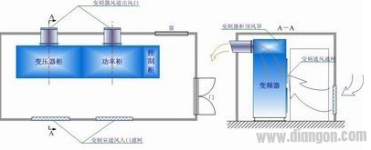
1.3 System Features
(1) Simple construction and easy maintenance
(2) Low cost
(3) Operational stability depends on local environmental conditions
2. Air Conditioning Closed Cooling
2.1 Capacity Selection Principle
The air conditioner capacity should be selected based on the heat generated by the inverter and the available space in the control room.
2.2 Installation Method
When installing the air conditioner in the inverter room, it is important to minimize the room size and ensure it is sealed to prevent external heat from affecting the internal environment. The air conditioner can be placed on either side of the inverter depending on site conditions, as shown in Figure 2. 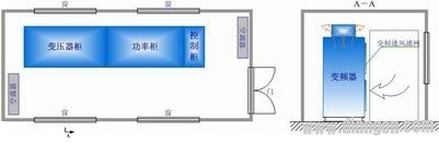
2.3 System Features
(1) Fast and efficient cooling
(2) Child lock function to prevent accidental operation
(3) Wide-angle air supply for even temperature distribution
(4) Anti-cold wind design for comfort
(5) Independent dehumidification
(6) Low temperature and low voltage start-up
(7) Outdoor unit capable of high-temperature operation
(8) Closed indoor cooling
(9) Extra cooling capacity reserved
3. Air-Water Closed Cooling
3.1 Basic Principles
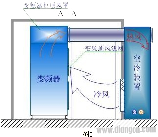
The air-water cooling system is an environmentally friendly, energy-efficient solution that is widely used in China. It uses a radiator and water-cooled pipes to cool the hot air from the inverter, as shown in Figure 3. 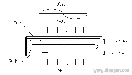
Hot air from the inverter is directed into the radiator, where it transfers heat to cold water below 33°C. The cooled air is then released, and the heat is carried away by the circulating water. This ensures that the ambient temperature in the control room remains below 40°C.
The air cooler must be installed in a closed environment. To maximize cooling efficiency, the equipment area should be minimized. Industrial circulating water is used, with a neutral pH value and no corrosive impurities. Water pressure is typically between 0.2-0.3 MPa, and the inlet temperature must be ≤33°C. Maintenance involves annual cleaning of the cooling pipes.
3.2 Construction and Installation
Each inverter is equipped with two air coolers. In case of a single fault, the system remains operational. The layout is shown in Figures 4 and 5. The air coolers can be placed on the front or back of the inverter, depending on site conditions. 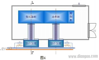
If the site lacks sufficient water supply, an independent cooling system can be added, including cooling towers, water treatment units, and booster pumps. This ensures adequate cooling for future equipment expansion. 
3.3 Safety Performance Evaluation
The air cooler is installed outside the high-voltage inverter room, directly connected to the inverter’s exhaust port, ensuring efficient cooling. This prevents potential damage from water leaks in high-pressure areas. The system includes safety features such as condensation prevention and a water spray plate to drain any leaks. These features enhance operational safety and reduce failure rates.
3.4 System Features
(1) Easy and fast installation
(2) Long service life and reliable performance
(3) Operating cost is 1/3–1/4 of similar systems
(4) Clean and hygienic indoor cooling
(5) No need for filter cleaning
(6) Can be used in emergencies without compromising safety
(7) Additional cooling capacity reserved
4. Equipment Body Water Cooling
While water cooling is highly efficient, it requires complex installation, extensive maintenance, and poses safety risks if leaks occur. Therefore, it is generally avoided unless absolutely necessary.
5. Comparison of Cooling System Indicators and Operating Costs
The table below compares various cooling methods in terms of investment, cooling effect, applicable range, and operating costs:
| Cooling Method | Investment | Cooling Effect | Applicable Range | Operating Cost (yuan/kW) |
|---|---|---|---|---|
| Air Duct Open | Low | General | ≤1600kW | 0.0291 |
| Air Conditioning Closed | High | Good | ≤1000kW | 0.178 |
| Air-Water Cooling | High | Good | ≤6000kW | 0.0458 |
| Equipment Body Water Cooling | High | Good | >6000kW | 0.089 |
III. Conclusion
Considering regional differences, temperature, humidity, and equipment safety, the principle of "suitable is best" guides the development of cooling solutions tailored to user needs. This ensures the highest level of safety, stability, and economic efficiency.
For high-power and ultra-high-power inverters above 1600 kW, the air-water cooling system remains a strong choice. In a 2×3400kW induced draft fan inverter project in a Shanxi power plant, this method proved its effectiveness and safety. It significantly improved product reliability, reduced energy consumption, and lowered maintenance costs, showcasing excellent economic benefits. In summary, the development and adoption of advanced cooling technologies are crucial for enhancing the reliability of high-voltage inverters.
Rj45 Connector,Modular Connector,Rj45 Router Net Instrument Connecting Connector
Dongguan City Yuanyue Electronics Co.Ltd , https://www.yyeconn.com