Thermocouple and cold junction compensation
A thermocouple is a differential temperature measurement device consisting of two different wires, one for the positive junction and the other for the negative junction. Table 1 lists the four most common types of thermocouples, metals used, and corresponding temperature measurement ranges. Two different thermocouple wires are welded together to form two junctions. As shown in Figure 1a, the loop voltage is a function of the temperature difference between the two junctions. This uses the Seebeck effect, which is usually described as the process of converting thermal energy into electrical energy. The Seebeck effect is contrary to the Peltier effect, which is a process in which electric energy is converted into heat energy, and a thermoelectric cooler is typically used. As shown in Fig. 1a, the measured voltage VOUT is the difference between the junction voltage of the detection junction (hot junction) and the junction voltage of the reference junction (cold junction). Because VH and VC are generated by the temperature difference between the two junctions, VOUT is also a function of the temperature difference. The proportional factor α corresponds to the ratio of the voltage difference to the temperature difference and is called the Seebeck coefficient.
Table 1: Several commonly used types of thermocouples.
Figure 1: a. The loop voltage is generated by the temperature difference between the two junctions of the thermocouple. b. The common thermocouple configuration consists of two metal wires connected at a junction. The open junction of each wire is connected to the copper thermostat.
Figure 1b shows one of the most common thermocouple applications. This configuration introduces a third metal (intermediate metal) and two additional junctions. In this example, each open-circuit node is electrically connected to a copper wire. These wires add two additional nodes to the system. As long as the temperatures of the two nodes are the same, the intermediate metal (copper) does not affect the output voltage. This configuration allows thermocouples to be used without separate reference junctions. VOUT is still a function of the temperature difference between the hot and cold junctions and is related to the Seebeck coefficient. However, since the thermocouple measures the temperature difference, the cold junction temperature must be known in order to determine the actual temperature of the hot junction. The cold junction temperature is 0°C (freezing point), which is the simplest case. If TC=0°C, then VOUT=VH. In this case, the hot junction measurement voltage is a direct conversion of the junction temperature. The National Bureau of Standards (NBS) provides a look-up table of the voltage characteristics of various types of thermocouples and temperature correspondences, all of which are based on cold junction temperatures of 0°C. Using the freezing point as a reference point, the hot junction temperature can be determined by finding the VH in the appropriate table.
In the early days of thermocouple application, freezing point was used as a standard reference point for thermocouples, but in most applications it is not practical to obtain a freezing point reference temperature. If the cold junction temperature is not 0°C, the cold junction temperature must be known in order to determine the actual hot junction temperature. Taking into account the non-zero cold junction temperature voltage, the thermocouple output voltage must be compensated, the so-called cold junction compensation.
Select cold junction temperature measurement device
To achieve cold junction compensation, the cold junction temperature must be determined, which can be achieved with any type of temperature sensing device. In common temperature sensor ICs, thermoelectric regulators, and RTDs, different types of devices have different advantages and disadvantages and need to be selected according to the specific application. For applications with very high accuracy requirements, calibrated platinum RTDs can maintain high accuracy over a wide temperature range, but at a high cost. When the accuracy requirement is not very high, the use of thermistors and silicon temperature sensor ICs can provide a higher price/performance ratio. Thermistors have a wider temperature measurement range than silicon ICs, while the temperature sensor ICs have a higher linearity and therefore performance. The indicator is better. Correcting the non-linearity of the thermistor consumes more microcontroller resources. The temperature sensing IC has excellent linearity, but the temperature measurement range is very narrow.
Therefore, the cold junction temperature measurement device must be selected according to the actual needs of the system, and the accuracy, temperature range, cost, and linearity index need to be carefully considered in order to obtain the best price/performance ratio.
Lookup table method
Once you have established a cold junction compensation method, the compensation output voltage must be converted to the appropriate temperature. A simple method is to use a lookup table from NBS. Implementing look-up tables in software requires memory to store, but these tables provide a quick and accurate solution when it comes to continuous testing. Two other methods for converting the thermocouple voltage to temperature require more than just a look-up table, both of which use a linear approximation of the polynomial coefficients and analog linearization of the thermocouple output signal.
Software linearity is popular because it does not require storage other than the predefined polynomial coefficients. The disadvantage of this approach is the processing time associated with multiple-order polynomials. For more order polynomials, the processing time increases further. For temperature measurement applications that require multiple polynomials, the lookup table may be more efficient and accurate than the linear approximation method.
Before the software used to implement the conversion from voltage to temperature (with the exception of manually searching the look-up table), analog linearization methods are commonly used. This hardware-based approach uses analog circuitry to correct the nonlinearity of the thermocouple response. Its accuracy depends on the order of approximation correction. This method is still widely used in those multimeters that receive thermocouple signals.
Application Circuit
Three typical applications for cold junction compensation using silicon sensor ICs are discussed below. All three circuits are used to solve cold junction temperatures with narrow temperature ranges (0°C to +70°C and -40°C to +85°C). Compensation, accuracy within a few degrees Celsius. The first circuit uses a temperature-sensing IC near the cold node to determine its temperature; the second circuit includes a remote-junction diode temperature detector, connected by a diode-connected transistor (connector directly connected to the thermocouple) The test signal is provided for it; the third circuit has an analog-to-digital converter (ADC) with built-in cold junction compensation. All three circuits use a K-type thermocouple (composed of a nickel-chromium alloy and a nickel-based thermocouple alloy) for temperature measurement.
1. Typical application
In the circuit shown in Figure 2, the 16-bit ADC converts the low-level thermocouple voltage to a 16-bit serial data output. The integrated programmable gain amplifier helps to improve the resolution of the A/D conversion, which is necessary to handle the thermocouple small-signal output. The temperature detection IC is mounted close to the thermocouple connector and measures the temperature near the cold junction. This method assumes that the IC temperature is approximately equal to the cold junction temperature. The cold junction temperature sensor output is digitally converted by channel 2 of the ADC. The 2.56V reference inside the temperature sensor saves an external voltage reference IC.
Figure 2: The local temperature detection IC (MAX6610) determines the cold junction temperature. The thermocouple and cold junction temperature sensor output voltages are converted by a 16-bit ADC (MAX7705).
When operating in bipolar mode, the ADC can convert the positive and negative thermocouple signals and output on channel 1. Channel 2 of the ADC converts the single-junction output voltage of the MAX6610 into a digital signal that is provided to the microcontroller. The output voltage of the temperature detection IC is proportional to the cold junction temperature. In order to determine the hot junction temperature, the cold junction temperature needs to be determined first, and then the cold junction temperature is converted into the corresponding thermoelectric voltage through the K-type thermocouple look-up table provided by the NBS. This voltage is added to the thermocouple reading calibrated with PGA gain, and finally the result of the summation is converted to temperature by a lookup table. The result is the hot junction temperature.
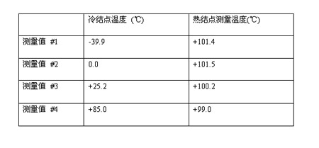
Table 2: The measurements are taken from the cold and hot junction temperatures in different ovens. Cold junction temperature range: -40°C to +85°C, hot junction temperature maintained at +100°C.
Table 2 shows the results of the temperature measurements. The cold junction temperature range is from -40°C to +85°C and the hot junction is maintained at +100°C. The accuracy of the actual measurement results depends to a large extent on the accuracy of the local temperature detection IC and the oven temperature.
2. Typical application II
In the circuit shown in Figure 3, the remote junction temperature detection IC measures the cold junction temperature of the circuit. Unlike the local temperature detection IC, the IC does not need to be installed close to the cold junction, but instead measures the cold junction through a diode-connected transistor externally connected. Point temperature. The transistor is mounted directly on the thermocouple connector. The temperature detection IC converts the measured temperature of the transistor to a digital output. Channel 1 of the ADC converts the thermocouple voltage to a digital output. Channel 2 is not used and the input is directly grounded. The external 2.5V reference IC provides the reference voltage for the ADC.
Figure 3: Installation temperature of remote junction diodes near cold junctions. The MAX6002 provides a 2.5V reference for the ADC.
Tables 2 and 3 show the results of the temperature measurement. The temperature range of the cold junction temperature is -40°C to +85°C, and the hot junction is maintained at +100°C. The accuracy of the actual measurement results depends to a large extent on the accuracy of the remote-junction diode temperature detection IC and the oven temperature.

Table 3: Measurements were taken from cold and hot junction temperatures in different ovens. Cold junction temperature range: -40°C to +85°C, hot junction temperature maintained at +100°C. The hot junction measurement in the table is compensated.
3. Typical application three
The 12-bit ADC in the circuit of Figure 4 is equipped with a temperature detection diode. The temperature detection diode converts the ambient temperature into a voltage. The IC calculates the compensated hot junction temperature by processing the thermocouple voltage and the diode detection voltage. The digital output is the result of compensating for the thermocouple test temperature. Within the temperature range of 0°C to +700°C, the device temperature error remains within ±9LSB. Although the device has a wide temperature measurement range, it cannot measure temperatures below 0°C.
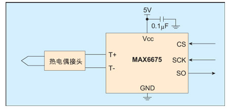
Figure 4: ADC with integrated cold junction compensation converts the thermocouple voltage to temperature without external components.
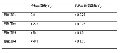
Table 4: Measurements were taken from cold and hot junction temperatures in different ovens. Cold junction temperature range: 0°C to +70°C, hot junction temperature maintained at +100°C. The hot junction measurement in the table is the decimal number provided by the circuit.
Table 4 shows the measurement results of the circuit shown in Figure 4. The cold junction temperature range is from 0°C to +70°C, and the hot junction temperature is maintained at +100°C.
Parabolic Reflex Reflector,Parabolic Grow Reflector,Aluminum Lamp Reflector,Safety Lighting Covers
Yangzhou Huadong Can Illuminations Mould Manufactory Co., Ltd. , https://www.light-reflectors.com