The design introduces a temperature control system based on the LM35 temperature sensor, focusing on the system structure, working principle, and sampling value quantification. It also covers the characteristics of the LM35 sensor, hardware circuit design, and software implementation. The system is compact, cost-effective, reliable, and has high practical value in engineering applications. With minor modifications or expansions, it can be adapted for various temperature measurement and control tasks.
**1. LM35 Temperature Sensor**
The LM35 is an integrated temperature sensor from National Semiconductor. It offers high accuracy and a wide linear operating range. Its output voltage is directly proportional to the Celsius temperature, making it more user-friendly than Kelvin-based sensors. The LM35 provides ±0.25°C accuracy at room temperature without the need for external calibration.
Key specifications include:
- Operating Voltage: 4V to 30V DC
- Operating Current: Less than 133μA
- Output Voltage: +6V to -1.0V
- Output Impedance: 0.1Ω at 1mA load
- Accuracy: 0.5°C at 25°C
- Leakage Current: Less than 60μA
- Scale Factor: 10mV/°C
- Nonlinearity: ±0.25°C
- Calibration Method: Direct Celsius calibration
- Package: TO-46 or TO-92 transistor package
- Operating Temperature Range: -55°C to +150°C
Pin configuration:
- Pin 1: Positive power supply (Vcc)
- Pin 2: Output
- Pin 3: Ground or power ground
**2. System Structure and Working Principle**
The temperature control circuit includes a sensor circuit, signal conditioning circuit, A/D sampling circuit, microcontroller system, output control circuit, and heating circuit. The sensor converts temperature into a voltage signal, which is then conditioned and converted into digital data by the A/D converter. The microcontroller processes this data and controls the heating circuit accordingly.
For example, if the temperature drops to 0°C or below, the system activates the heating circuit. If it rises above 0°C, the heating stops. This is an open-loop control system.
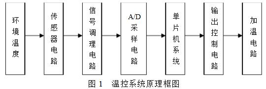
As shown in the diagram, when the ambient temperature falls below 0°C, the microcontroller outputs a low-level signal, activating the relay and turning on the heating circuit.
**3. Core Hardware Circuit Design and Sampling Value Quantification**
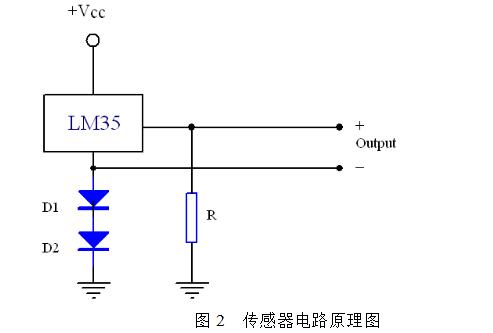
The core component of the sensor circuit is the LM35AH. When powered with 15V DC, it consumes only 120mA, making it energy-efficient. The output uses a differential signal mode through pins 2 and 3. Resistors R = 18kΩ and diodes D1, D2 = 1N4148 are used in the circuit. This setup is suitable for temperatures ranging from -55°C to +150°C.
The signal conditioning circuit amplifies and limits the sensor signal, converting it into a DC voltage of approximately 2V, which is then regulated to ±10V using an LF412 operational amplifier. The A/D sampling circuit uses a 12-bit AD574 converter. The microcontroller system is based on the AT89C55, with external latches and drive circuits. The output control uses a Panasonic PhotoMOS relay AQZ202, while the heating circuit uses a power resistor designed to operate at 28V DC with a total resistance of about 14Ω, providing 50W of heating power.
Accurate quantization of the sampled values is crucial for proper system operation. Assuming the conditioned voltage Ui ranges from -10V to +10V, corresponding to temperatures from -55°C to +125°C, the proportional factor Kt = 0.111V/°C is calculated. At 0°C, the voltage is -3.895V. Using a 12-bit ADC, each digital unit corresponds to 4.883mV. The conversion factor between digital units and temperature is approximately 22.73 digital units per °C. Thus, at 0°C, the digital output is 1250 (0x4E2).
**4. System Software Design**
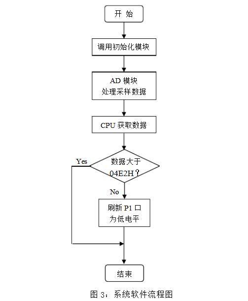
The software is written in PLM/51 and ASM mixed programming, using a modular structure that includes main, AD sampling, initialization, timer, and error handling modules. This makes the system easy to maintain and modify.
The AD converter is connected via interrupt mode to the AT89C55 microcontroller. After conversion, the CPU reads the digital value and compares it to the threshold of 0x4E2 (corresponding to 0°C). If the value is higher, the P1 port is set to low, activating the relay; otherwise, it remains high.
To prevent errors due to interference, the software includes filtering techniques. It samples five times, removes the maximum and minimum values, and averages the remaining three for more accurate readings.
The system has been tested extensively and proven stable and reliable. It features a small size, high sensitivity, fast response, and strong anti-interference capability. Being low-cost and using common components, it has high engineering value and has been applied in certain UAV flight control systems. With slight adjustments, it can be expanded into a product that integrates both temperature measurement and control. Additionally, the small nonlinearity of the LM35 can be corrected using software algorithms.
Chamfered Radiator,Galvanized Chamfered Radiator,Corrosion Resistant Chamfered Radiator,Power Transformer Chamfered Radiator
Shenyang Tiantong Electricity Co., Ltd. , https://www.ttradiator.com