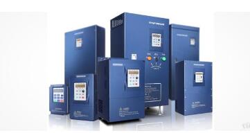
Frequency conversion speed regulation technology is a key development direction in modern electric drive systems. As the core component of variable frequency speed control systems, the performance of the inverter plays a crucial role in determining the overall speed control capability. Beyond its inherent manufacturing process, the way the inverter is controlled also significantly impacts its performance. Based on real-world industrial applications, this article reviews various inverter control methods and explores their future development trends.
**Introduction to the Inverter**
1) **Basic Structure of the Inverter**
An inverter is a device that converts standard AC power (50 Hz or 60 Hz) into adjustable frequency AC power to enable variable-speed motor operation. The control circuit manages the main circuit, while the rectifier converts AC to DC. The DC link circuit smooths the rectified output, and the inverter circuit then converts DC back into AC. For advanced inverters like vector-controlled ones, which require complex calculations, a CPU for torque computation and related circuits may be necessary.
2) **Classification of the Inverters**
Inverters can be classified in multiple ways. By main circuit operation mode, they are divided into voltage-source and current-source inverters. Based on switching mode, they include PAM, PWM, and high-frequency PWM inverters. According to working principles, they fall into V/f control, slip frequency control, and vector control inverters. By purpose, they are categorized as general-purpose, high-performance special, high-frequency, single-phase, and three-phase inverters.

**Basis for Choosing Inverter Control Modes**
The choice of control method depends on the specific requirements of the production equipment.
1) **Quadratic Load**
For loads such as centrifugal fans, water pumps, and air compressors, V/f control is typically suitable. This mode offers lower excitation U/f ratios, saving energy at low frequencies. Vector control maintains rated flux but cannot operate with low excitation.
2) **Constant Torque Load**
- For loads with frequent load changes and small speed ranges, no feedback vector control is preferred. However, it requires accurate motor parameter self-measurement.
- If the minimum operating frequency is below 5 Hz, check the inverter's low-frequency stability.
- For stable loads, V/f control can be used with a cheaper general-purpose inverter.
3) **Constant Power Load**
- Winding machines can use V/f or no feedback vector control.
- Metal cutting machines, requiring high dynamic response, benefit from feedback vector control.
**Detailed Description of Inverter Control Methods**
1) **U/f=C Sinusoidal Pulse Width Modulation (SPWM)**
SPWM is known for its simple structure, low cost, and good mechanical characteristics, making it suitable for general speed regulation. However, at low frequencies, stator resistance voltage drop reduces torque, leading to lower maximum output. It lacks the hardness of DC motors and has poor dynamic performance.
2) **Voltage Space Vector Pulse Width Modulation (SVPWM)**
SVPWM generates three-phase waveforms to approximate a circular magnetic field. It improves accuracy through frequency compensation and flux estimation. However, it lacks torque adjustment, limiting performance improvement.
3) **Vector Control (VC)**
Vector control transforms three-phase currents into two-phase coordinates and aligns them with the rotor’s magnetic field, mimicking DC motor control. This allows independent control of speed and flux. However, rotor flux observation is challenging, and system performance is sensitive to motor parameters.
4) **Direct Torque Control (DTC)**
Proposed by DePenbrock in 1985, DTC directly controls motor flux and torque without DC motor equivalence. It simplifies calculations and improves dynamic response. It is widely used in high-power drives, offering fast torque response and high accuracy.
5) **Matrix Control Mode**
This method eliminates the DC link, reducing size and cost. It achieves a power factor of 1, operates in four quadrants, and provides high power density. Though not yet fully mature, it attracts significant research interest due to its direct torque control capabilities.
**Key Features of Matrix Control:**
- Stator flux linkage is observed for sensorless control.
- Automatic identification (ID) uses accurate motor models.
- Real-time calculation of torque, flux, and speed based on motor parameters.
- Band-Band control generates PWM signals to manage inverter states.
Matrix AC-AC inverters offer fast torque response (2ms), high speed accuracy (±2%), and excellent low-speed performance, capable of delivering 150–200% torque even at zero speed.
While this overview covers the essentials, a deeper understanding of inverters requires practical application and continuous learning. As the saying goes, "Practice makes perfect."
Water Heater Breaker
Leakage protector, also known as leakage switch, is a new type of electrical safety device, mainly used for:
(1) Prevent electric shock accidents caused by electrical equipment and electrical circuit leakage;
(2) Preventing single-phase electric shock accidents during electricity use
(3) Timely cut off single-phase grounding faults in the operation of electrical equipment to prevent fire accidents caused by leakage
(4) With the improvement of people's living standards and the continuous increase of household appliances, personal electric shock and fire accidents caused by defects, improper use, and inadequate safety measures of electrical equipment in the process of using electricity have brought undue damage to people's lives and property. The emergence of leakage protectors provides reliable and effective technical means for preventing various accidents, timely cutting off power, and protecting equipment and personal safety.
The leakage protector should meet the following technical requirements
(1) The sensitivity of electric shock protection should be correct and reasonable, and the starting current should generally be within the range of 15-30 milliamperes
(2) The action time of electric shock protection should generally not exceed 0.1 seconds
(3) The protector should be equipped with necessary monitoring equipment to prevent it from losing its protective effect when the operating state changes. For example, for voltage type electric shock protectors, a neutral grounding device should be installed.
ZHEJIANG QIANNA ELECTRIC CO.,LTD , https://www.traner-elec.com