**Introduction to ICL7107 and Pin Diagram**
The ICL7107 is a dual-slope analog-to-digital (A/D) converter, which belongs to the category of indirect A/D converters. It performs two integrations: one on the input voltage and another on the reference voltage. The average value of the input voltage is converted into a time interval proportional to it, and this time interval is then used to generate a corresponding digital output.
The device includes an integrator, comparator, counter, control logic, and clock source. The integrator is the core component of the A/D converter. During each measurement cycle, it integrates both the input signal voltage and the reference voltage. The comparator compares the integrator's output with a zero level, and this comparison result serves as a control signal for the digital circuitry.
The standard clock period Tc is used as a timing reference for the measurement process. This clock is generated using two internal inverters and an external RC network. The counter counts the clock pulses during the reverse integration phase. The control logic consists of dividers, decoders, phase drivers, controllers, and latches. The frequency divider is used to reduce the clock frequency to produce the required counting pulse fc and square wave signal for driving the common anode LED display.
**Features of ICL7107**
1. The ICL7107 is a 3½-bit dual-slope A/D converter, part of the CMOS LSI family. It can display values up to ±1999, with a resolution of 100 µV and a conversion accuracy of 0.05% ± 1 digit.
2. It directly drives a common anode LED display without requiring additional driver circuits, simplifying the overall design. It operates on two 5V power supplies, and the GND pin (pin 21) should be connected to the IN pin (pin 30).
3. A stable 2.8V internal reference voltage is available between V+ and COM. The reference voltage VREF can be obtained through a resistor divider.
4. It supports automatic zero adjustment and polarity display via internal analog switches.
5. The input impedance is high, ensuring no signal attenuation.
6. The system is easy to assemble, requiring only resistors, capacitors, and an LED display to form a DC digital voltmeter.
7. It has low noise, minimal temperature drift, high reliability, and a long operational life.
8. The chip consumes less than 15 mW (excluding LEDs).
9. No special decimal point drive signal is needed; the common anode of the LED display can be connected directly to V+.
10. It offers convenient function testing capabilities.
1) Polyester enameled aluminum wire, class 130
2) Modified polyester enameled aluminum wire, class 155
3) Polyesterimide enameled aluminum wire, class 180
4) Polyester (imide) coated with polyamide-imide enameled aluminum wire, class 200
5) Polyimide enameled aluminum wire, class 220
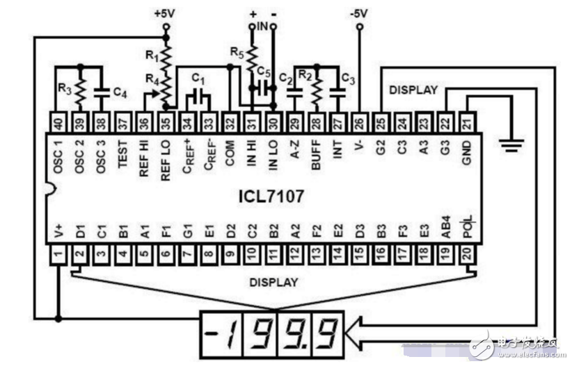
Figure 1: ICL7107 pin diagram and typical circuit
**Pin Functions of ICL7107** - **Au, aT, aH**: Drive signals for the units, tens, and hundreds digits of the LED display. - **Bck**: Drive signal for the thousands digit of the LED display. - **PM**: Back electrode drive for the liquid crystal display. - **Oscl–Oscl3**: Oscillator terminals, which can use an external resistor or quartz crystal. The capacitance between pins 38 and 40 is calculated using Fosc = 0.45 / RC. - **COM**: Analog ground, usually connected to the negative terminal of the input signal and reference voltage. - **TEST**: Test terminal connected to the logic ground through a 500 Ω resistor. - **VREF+ and VREF–**: Positive and negative reference voltage terminals. - **CREF**: External reference capacitor terminal. - **INT**: Integrating capacitor terminal. The input signal is connected to IN+ and IN–, which must have a low temperature coefficient. - **AZ**: Inverting input of the integrator and comparator, connected to the auto-zero capacitor CAZ. - **BUF**: Buffer amplifier output, connected to the integrating resistor Rint. It provides 20 µA of drive current. **Interface Design Between ICL7107 and 8031** The ICL7107 is a 3½-bit dual-slope A/D converter designed by Intersil for digital instrumentation. It requires minimal external components to form a peripheral circuit, making it ideal for building sophisticated digital instruments. It offers high resolution and strong anti-interference capability, making it widely used in applications where performance and cost are key factors. While it can directly drive an LED display, it lacks BCD output and status flags, making it incompatible with microcomputer systems for data collection. This paper presents a simple method to interface the ICL7107 with the 8031 microcontroller, expanding its functionality and application scope. **Analysis of Interface Conditions** The A/D conversion cycle of the ICL7107 consists of three phases: the integration (INT) phase, the elimination integration (DE) phase, and the autozero (AZ) phase. One full conversion cycle lasts 4000 count pulses. During the INT phase, the input voltage is integrated over 1000 count pulses. In the DE phase, the reference voltage is reversed and counted. The count value is linearly proportional to the input voltage, ranging from 0 to 2000. The autozero time varies between 3000 and 1000 count pulses depending on the input voltage. The internal count pulse frequency is divided by 4 relative to the ICL7107’s clock frequency. A status signal at pin 34 (CREF’) can be used as a handshake signal for the interface. This signal is low during the INT and DE phases and high during the AZ phase. By converting this signal to TTL levels compatible with the 8031, a simple interface can be implemented. **Interface Design and Implementation** The interface circuit uses three port lines of the 8031. Port T is set to mode 1, while INTO and P1.0 receive the level-converted A/D conversion state signal and the polarity signal, respectively. The polarity of the input signal is typically known, so the P1.0 line can often be omitted. The GATE bit is set to 1, allowing the INTO pin to act as a gate for the timer. When INTO is high, the timer counts the ICL7107 clock, and stops when INTO is low. An external interrupt 0 is triggered on the edge. The count value is read and processed in the interrupt service routine. Since the internal clock is divided by 4, the final binary result is obtained by dividing the count value by 4 and subtracting the inherent 1000 counts from the integration stage. **Reference Procedure** The interface method described in this paper involves counting the clock pulses during the ICL7107’s integration and elimination phases. The 8031 timer counts these pulses, and the count value is adjusted accordingly. The resulting binary value represents the A/D conversion result. While the internal count is used for decoding and display, the 8031 reads the counter value to obtain field data for the intelligent instrument. The results from the 8031 match the LED display driven by the ICL7107. This method is also applicable to other ICL A/D converters with display drivers, such as 7106, 7116, 7117, 7126, 7129, and 7137.| About Film Covered Flat Copper Wire |
1) Polyester enameled aluminum wire, class 130
2) Modified polyester enameled aluminum wire, class 155
3) Polyesterimide enameled aluminum wire, class 180
4) Polyester (imide) coated with polyamide-imide enameled aluminum wire, class 200
5) Polyimide enameled aluminum wire, class 220

Sweet safe packing are available
• Professional production and sales Team
• Double or Three Type Insultaions covered wires
Covered Copper Wire,Film Covered Flat Copper Wire,Non Woven Covered Copper Wire,Polyester Film Covered Copper Wire
HENAN HUAYANG ELECTRICAL TECHNOLOGY GROUP CO.,LTD , https://www.huaonwire.com