When using any new technology, the biggest challenge for production engineers is what to test and why to test them. This is especially tricky for complex devices such as modern smartphones or tablets. As for LTE, the complexity is unprecedented. If you test it completely, you need to put the device on the tester all day.
The basic assumption in production must be that the engineering department delivers a design that meets all of the customer's needs and that achieves consistent functionality after proper assembly. While supporting this assumption adds to the burden on the design team and its processes, without this guarantee, the testing range will be too large to detect all the possibilities for today's extremely complex equipment. The production floor is not the place to test millions of firmware lines or to verify hardware capabilities associated with the design of millions of gate-level digital signal processing (DSP) / application specific integrated circuit (ASIC) designs.
The main goal of production testing is to test as many mobile devices as possible, to identify manufacturing defects while minimizing test time. Software and digital design have been validated in engineering and compliance testing. Digital integrated circuits have been extensively tested in their production processes. In the event of a digital failure, it often causes catastrophic consequences such as the inability to power on the phone, the inability to produce an output, or the inability to receive a signal. These faults are usually best discovered by simple techniques such as internal power-up tests and by using checksums without any tester intervention at all. Therefore, optimal production testing focuses on physical layer measurements, which demonstrates the greatest degree of variability associated with the manufacturing process.
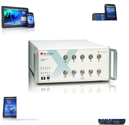
The following sections discuss LTE testing and how to optimize tests for physical layer testers such as LitePoint's Iqxstream, see figure.
Physical layer measurement
Physical layer testing focuses on the lowest level of the air interface. The goal is to determine the consistency of important parameters that are essential for successful transmission of wireless signals. Transmit power, transmit waveform quality, and transmit frequency accuracy are critical to the performance of mobile stations. At the receiving end, the ability of the mobile device to successfully decode the received signal at the lowest and highest signal levels is key to its successful operation in the network.
The 3GPP test specification for LTE contains a number of different test tools to determine the conformance of the LTE specifications. There are a number of overlaps in many of these tests. Given the degree of implementation within the digital domain, many measurements between one mobile device and another will not differ. The User Equipment (UE) Transmitter (Table 1) test is generally considered sufficient to detect problems in the production environment.
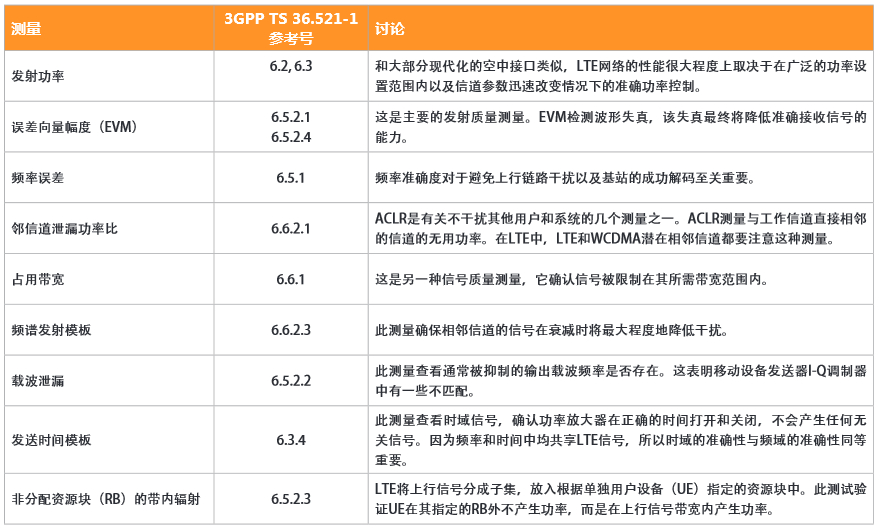
Table 1: UE Transmitter Measurement Indicators
To a large extent, the adjacent channel leakage power ratio (ACLR), occupied bandwidth, and spectrum emission template (SEM) all solve the same problem. Typically there is some degradation in the final part of the analog output link, or there is a noise source in the DUT that generates spurious signals. Therefore, only one of these measurements will be specified as part of the test plan.
Unlike the transmit link where the final output is located at the antenna connector for evaluation, the received signal is always inside the DUT until it is fully decoded. Fortunately, although there are many devices that may degrade in the receive chain, almost all of the degradation will be shown in the receive error rate measurements at or near the receive threshold. Physical layer testers typically rely on the ability of the DUT to report the receipt of test results. Since reception quality monitoring is an important part of modern air interface operation, routing this data to an external terminal interface is a straightforward method. Most, if not all, integrated circuit manufacturers support some or other forms of bit error rate testing.
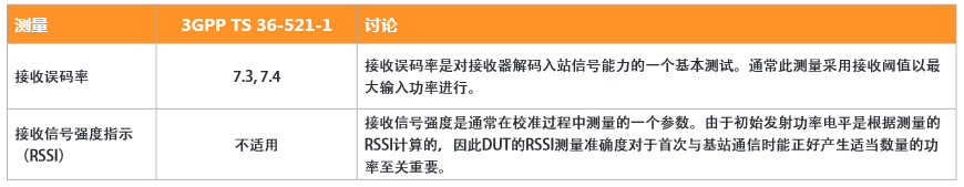
Table 2: UE Receiver Measurement Indicators
The two tests in Table 2 are used to verify reception performance. With the combination of the above measurements, the challenge now becomes how to apply them to almost unlimited possibilities for mobile device configurations.
LTE test plan development
There are many ways to develop a test plan, including: looking for possible failure modes in the design; using standard agency recommendations; recommendations from IC manufacturers; past history of similar devices in production.
Unfortunately, for new technologies like LTE, the experience that can be used as the basis for building a test plan can be very limited. Manufacturers of various devices may not disclose details within the design, and manufacturers may have limited experience with relatively new designs.
As a result, manufacturers often develop their own test plans and may retreat to the standards body's test specifications as a benchmark.
Table 3 represents a test plan developed for the LTE user equipment transmitter. Although we would like to perform several other tests and announce that the device under test (DUT) is "qualified" in production testing, this subset is very useful for this discussion.
Each column of Table 3 represents a test configuration from left to right, with each configuration being specified by the parameters at the top of each column. In general, when discussing the test configuration, we discuss the steady state where the DUT is located, such as constant modulation rate and constant power level. The lower half of each column represents the measurements to be made for each configuration.
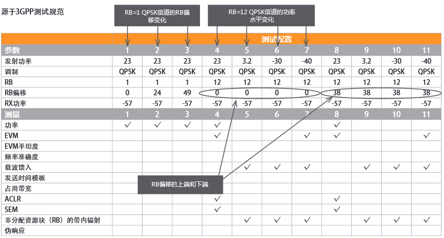
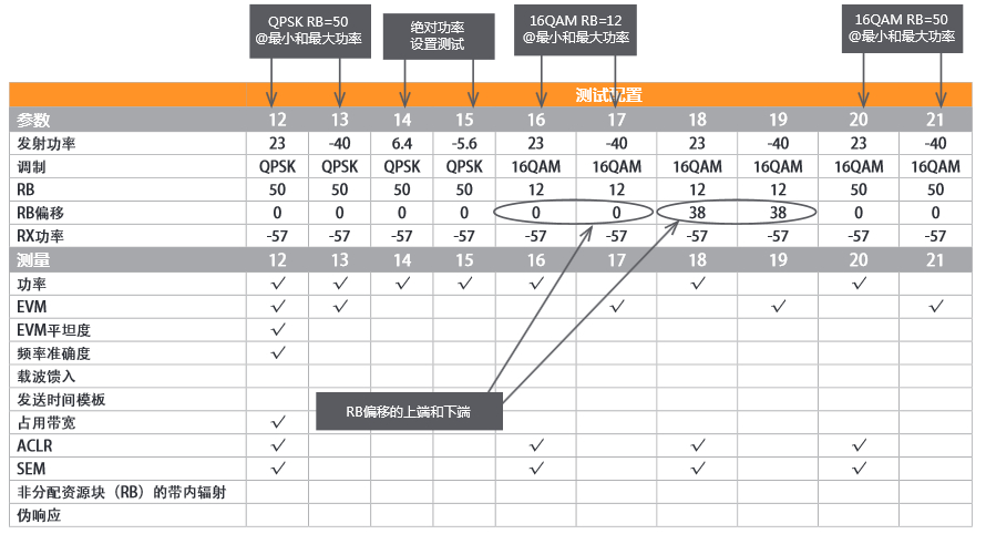
Table 3: Test Specifications from 3GPP
In Table 4, we will follow the development section of this test plan. The test developers in this case have extensive LTE knowledge and a good understanding of the 3GPP test specifications for LTE - he is considered an expert in testing other technology mobile devices.
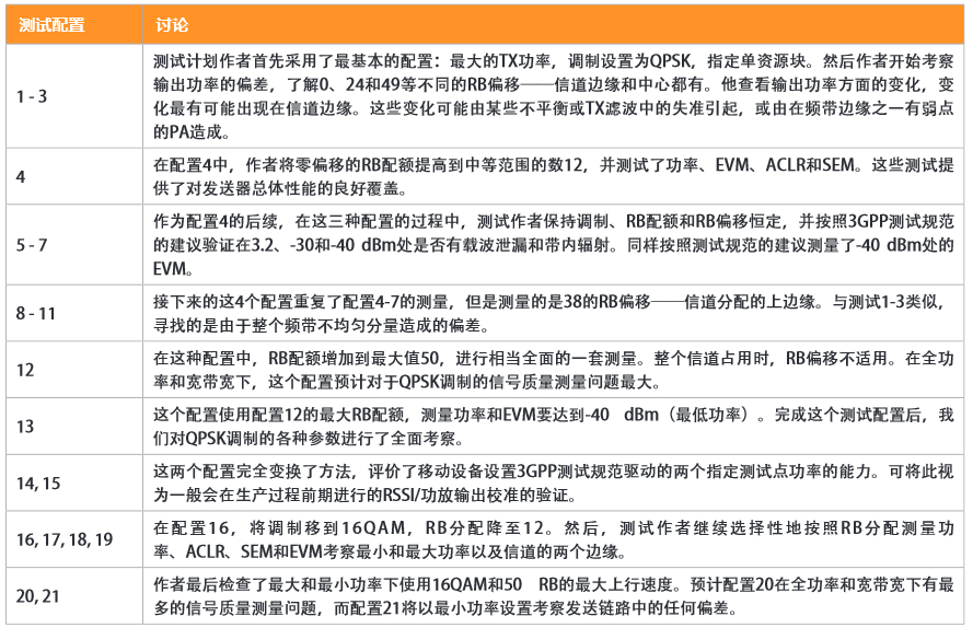
Table 4: Discussion of test specifications derived from 3GPP
Note that the author used an RX power level of -57dBm for all tests. Since the RX power is not directly related to the TX measurement, there is no problem no matter what level it is set to.
Note: It is generally assumed that the test plan will be consistently applied to various frequency bands/channels in accordance with the capabilities of the DUT. The 3GPP recommends testing the device with low, medium and high channels for each band. According to certain channel quotas, this may mean that only a single channel is tested.
From the perspective of test coverage, the author of the test plan did a good job: testing the performance boundaries of the DUT. He tested the maximum and minimum RB (resource block) allocations, the maximum and minimum modulation rates, and the maximum and minimum power levels. He examined the changes in the entire channel according to the RB allocation. This test is taken from the recommendations of the 3GPP test specification and is fully compatible with it. This type of test plan in production is unlikely to miss many problems (if any).
Let's check this test plan in terms of test throughput, because our goal is to test the DUT as efficiently as possible. When you look at this plan, two things are very prominent. The table is very sparse, but the number of configurations is very large.
Given that Iqxstream supports a method of data capture and analysis separation, the test time is largely determined by the configuration capture period, rather than by the number of measurements per capture calculation. This shows that the test plan optimized for throughput should minimize the number of configurations and increase the number of measurements. This tends to measure narrower tables with greater density.
Let us also check how the test engineer chooses different configurations. In the above example, the test completely examines a set of parameters and then orthogonally transfers to the next set. Tests 1~3 completely examined the changes in RB offset, then changed the RB block size, and examined the effects of different offsets again. In a laboratory environment, this control is critical to tracking the source of unacceptable changes in the design, but in a manufacturing test environment, this orthogonality is less important.
Simple defect example
Take a simple example to see how the defects in the simulation performance occur. Assuming that the post-modulation analog filter is frequency offset, the cutoff frequency invades the upper edge of the channel. The result will be that the power output will be low at the upper edge of the channel. This fault is shown in both the 1RB test and the 12RB test on the upper side of the band, which is the power measurement in test configurations 3 and 8. The fault can also be displayed in the EVM flatness measurement of the 50RB block.
Remember, in production we just want to determine if the DUT is "good" or "bad." Once it is identified as "bad", this DUT can be set aside for further inspection and repair. If isolation problems can significantly increase test time, then you don't need or should let the production line use the tests required for these isolation problems.
Configurations 3 or 8 in the test table can then be logically deleted because they provide similar test coverage. These types of repetitions often occur throughout the test plan. While some repetition may be necessary or necessary, it should not be wasted.
Neon Moon Light,Neon Ceiling Lights,Flexible Tube Lighting,Yellow Neon Light
Tes Lighting Co,.Ltd. , https://www.neonflexlight.com