A two-dimensional code is a symbol that records information in a two-dimensional direction of a plane. It makes full use of the two-dimensional space on the plane, greatly increasing the information density, making it possible to encode big data on a small area. Secondly, due to its superior error correction capability, it can be accurately identified even if it is damaged in a large area. QR codes are now used in industrial automation, logistics, postal, medical, commercial, financial, transportation, identification, government management, public safety, customs and defense. In China, the application of QR code is still in its infancy, and the application areas and fields are quite limited. However, it can be foreseen that the two-dimensional code will be promoted and applied in various fields in China like a barcode with its unique advantages.
This article refers to the address: http://
In this paper, Matrox's image acquisition card Meteor-II Standard uses the MIL function library to capture and recognize the Data Matrix QR code on the metal parts in real time, and perform specific image processing on the collected Data Matrix images. Name it to meet the identified requirements. Finally, the method of improving the recognition rate is discussed through experiments.
1 Data Matrix Overview
There are many types of QR codes. This article only discusses the Matrix Data Matrix.
The Data Matrix's biggest feature is "small", which encodes 30 digits on a 25mm2 area, so it is widely used to mark small items such as integrated circuits and pharmaceuticals. In addition, in the manufacturing process of the manufacturing line, it is easier to print and generate the Data Matrix.
As shown in Figure 1, the Data Matrix symbol looks like a chess board consisting of two shades of color. Each black or white square of the same size is called a data unit. The Data Matrix symbol consists of many such data units. In the outer layer of the edge finding area, there is a quiet zone with a width of one data unit. The edge finding area is the boundary of the "checkerboard" and is only used to locate and define the size of the numeric unit without any coding information. The data area surrounded by the edge finding area contains the encoded information. 0, 1 in the matrix is ​​the black and white square of the Data Matrix, which is the data unit.
Data Matrix uses Reed-Solomon interleaved interleaving coding, and the error correction code is added to the coding, which makes the Data Matrix's error correction performance stronger. Taking a 5-bit serial number "12345" as an example, the 3-bit codeword and 5-bit error correcting code of the Data Matrix are obtained by the encoding rule, and the 2-bit codeword can be corrected, and the error correction rate is 2/8=25%.
2 Identify the Data Matrix code with MIL
The Meteor-II Standard is an image capture card from Matrox that captures external images through the camera and transmits them to the host memory in real time. The MIL Function Development Kit is a hardware-independent 32-bit image processing function library with a large number of basic image processing functions.
2.1 Basic process
The basic process identified by the Data Matrix is ​​shown in Figure 2. The image is acquired by the function provided by MIL, and the acquired image is digitally stored in the image buffer; the image is enhanced to improve the recognition accuracy of the image. In the experiment, the smoothing filtering method is used to reduce the image noise, which is a good solution to the problem of image segmentation caused by the brightness of the edge of the code symbol when the Data Matrrix code of the metal part is collected. Then the histogram equalization is performed on the image to expand the contrast dynamics. The range solves the problem that the collected image is dark due to illumination or the camera, and the contrast is not significant enough, causing the problem that the image is blurred.
Since the acquired image has a lot of useless background, the area where the Data Matrix symbol is located only accounts for a large proportion of the entire image. Using the mask method, the image processing area is limited by a fixed position sub-buffer, and the image outside the area is ignored, and the symbol extraction of the Data Matrix is ​​realized. Finally, the MIL function is used to directly decode, and the decoding result is placed in the specified string, and the result is printed on the screen with the display statement.
2.2 Data Matrix Symbols
The Data Matrix code on the metal part is a dot matrix of pneumatic printing, which is not exactly the same as the standard Data Matrix symbol, and the gap between the points is large. If the code is identified without processing, the recognition rate will be low. In order to solve this problem, a mathematical morphology expansion algorithm is employed. To improve recognition accuracy, the Data Matrix symbol can be expanded several times to reduce the gap between data units. This makes it much easier for the computer to "find" the Data Matrix's "L" edge-finding area.
2.3 Implementation of pseudo real-time recognition
Since MIL itself does not support real-time processing of images, real-time recognition requires pseudo-real-time image processing using a method called buffering. The image processed by the CPU is actually the previous frame image captured by the camera.
The double buffer makes it possible to process images while acquiring images, as shown in Figure 3. The camera collects the image into the image buffer 1 for processing, and at the same time, the CPU uses the time to process the image in the image buffer 2 (previous frame), and the functions of the two buffers are exchanged; the CPU processes the buffer 1 The image of the previous moment collected in the middle, and at this time the image in the buffer 2 has been processed, and the acquired image of the next frame of the camera can be received. In this way, the two buffers are interchanged, and the pseudo-real-time processing can be realized without moving continuously. Data Matrix recognition can be added to the processing link to realize real-time identification of the Data Matrix. The acquired image and the processed image are exactly one frame apart, so they are “pseudo†real-time, but if the computer is fast enough, the effect of the time delay can be ignored.
The advantage of this method is that it realizes real-time performance, and separates the two processes of acquisition and processing, allowing the CPU and camera to process independently and in parallel, making full use of idle time.
3 Identification results statistics and analysis
Through programming, the Data Matrix code on the metal is identified, and the total number of collected frames (f), frame rate (f/s), total number of frames successfully recognized, and recognition rate are counted. The experiment proves that the recognition rate is very high when the focal length of the camera and the light source are quite ideal.
The success rate of Data Matrix recognition is related to many factors. First, the Data Matrix symbol itself is printed on paper and is very different from the dot matrix Data Matrix printed on metal parts. Secondly, the motion distortion during detection will affect the recognition success. Rate; again, the influence of the background image, the greater the contrast between the Data Matrix symbol and the background color, the less the interference image in the background, the higher the recognition success rate; the rotation of the light source and the symbol will affect the recognition.
3.1 Impact of motion detection
Data Matrix detection is commonly used on the assembly line. In this case, the influence of the relative motion of the camera and the detected part on the recognition needs to be considered. In the experiment, the motion detection in the pipeline was simulated by fixing the parts and moving the camera, and the moving speed of the camera at each detection was recorded to find out the maximum relative running speed of the Data Matrix on the part.
Now 20 sets of data were measured by experiment, taking 6 mm × 6 mm Data Matrix as the object of consideration. The results are shown in Table 1.
As a result, in the case of ideal illumination and camera focus, the maximum recognition relative speed is 2.00 cm / s, faster than this speed may be caused by motion distortion caused by the Data Matrix is ​​not recognized.
3.2 Influence of interference image
Under the same conditions, the image recognition rate with less background interference is higher, especially when Beijing has a rectangular shape similar to the Data Matrix. Test the Data Matrix recognition rate on metal parts under good lighting conditions. In the case of background interference and the use of sub-buffers to mask some background interference, 10 sets of data were measured, as shown in Table 2.
Table 1 Effect of relative motion of the Data Matrix and camera to be tested on recognition 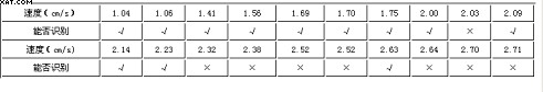
It can be seen that after the buffer is used to mask some useless background images, the recognition effect is generally better than unmasked.
3.3 Influence of light source
The effect of the light source on the recognition success rate is reflected in the light and dark contrast of the image as a whole. For the Data Matrix on metal parts, it is more about affecting the clarity of the symbols. If the position of the light source is not selected properly, due to the reflective properties of the metal, a very large specular reflection area will be formed on the metal surface, causing strong interference to the Data Matrix image.
A better way is to use a sidelight approach. Since the Data Matrix code on the metal parts is produced by pneumatic printing, there will be high and low fluctuations in the printing area. The reflection in these areas is warm reflection. Different from the specular reflection light in other areas, the side light helps to reflect the background of the lattice and the metal. Separately, the camera is shielded from the specular reflection of the metal. Figure 4 compares the two-dimensional code states under side and reflected light.
3.4 Adaptation procedure adaptability
The adaptability of the recognition program refers to the ability to adapt to different sizes and print types of Data Matrix. The types of printing considered in this paper are metal surface pneumatic printing, metal surface electric needle printing and standard paper laser printing. The experimental results show that the program's recognition ability for the pneumatically printed Data Matrix code is generally better than that of the metal needle-printed Data Matrix code. The recognition rates for different sizes are basically equal. The standard Data Matrix printed on paper can be recognized by the computer without too much image enhancement and expansion due to factors such as graphic standard, color stability, and high resolution. The recognition rate is very high.
VGA Splitter,VGA Switch,24 Port VGA Splitter
HDMI Splitter,HDMI Extender Co., Ltd. , http://www.nshdmicable.com