Digital Grounding Resistance Tester Manual and Usage Guide
When using a digital grounding resistance tester, it's important to follow the correct procedures to ensure accurate measurements. Let’s break down the steps for various types of measurements:
1. **Grounding Resistance Measurement**
(Refer to Figure 1 for visual guidance.)
To measure grounding resistance, arrange three probes—E (or C2/P2), P1, and C1—in a straight line in the ground. The spacing between each probe should be approximately 20 meters, with the potential probe (P1) positioned midway between the grounding electrode (E) and the current probe (C1). Insert the probes into the soil at the required depth. Next, connect the tester’s terminals to the corresponding probes using dedicated cables. Switch on the tester by pressing the "ON" button and choose an appropriate range. Once the indicator light turns on, the LCD will display the measured grounding resistance value.
2. **Soil Resistivity Measurement**
(Refer to Figure 2 for setup illustration.)
For soil resistivity testing, place four probes evenly spaced in a straight line within the soil you wish to measure. Ensure the distance between each probe equals L, and bury the probes to a depth of L/20 cm. Connect the tester’s terminals to the respective probes via wires. After activating the tester, record the resistance value (R) displayed on the meter. The soil resistivity (Ф) can then be calculated using the formula:
**Ф = 2πRL**, where:
- Ф represents soil resistivity (in Ω·cm),
- L is the distance between probes (in cm),
- R is the measured resistance (in Ω).
This method provides an approximate average resistivity for the area between the probes. The probes typically consist of aluminum alloy tubes or round steel rods measuring 25 mm in diameter and ranging from 0.25 to 1 meter in length.
3. **Conductor Resistance Measurement**
(Refer to Figure 3 for setup details.)
Conductors can also be tested using the same device. Follow the manufacturer’s instructions to set up the connections properly before taking measurements.
4. **Ground Voltage Measurement**
Similar to grounding resistance measurement (refer back to Figure 1), remove the C1 plug and retain the connection between E and P1. Activate the ground voltage (EV) mode, and the indicator light will illuminate. The reading on the meter indicates the AC ground voltage between E and P1.
5. **Final Steps**
After completing your measurements, switch off the tester by pressing the "OFF" button. Always ensure the device is powered down when not in use to preserve battery life and prevent accidental damage.
This guide covers the basic functions of the digital grounding resistance tester. Always refer to the user manual for specific details about your model and additional safety precautions. Proper usage ensures reliable results while maintaining the longevity of your equipment.
Super AC Contactor
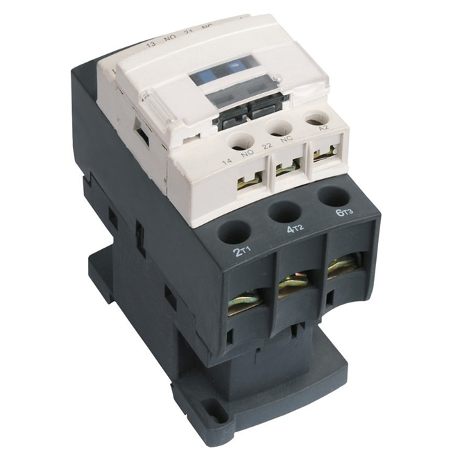
Super AC Contactor is exactly copy schneider newest model.The up parts and base will be easy opened to change the coils. On the top of Magnetic AC Contactors, there is a transparent cover for dust improved purpose.
Super AC Contactor is suitable for using in the circuits up to the rated voltage 660V AC 50Hz or 60Hz,rated current 95A.It's mainly used for making and breaking electric circuits at a long distance and for frequent starting/stopping & controlling AC motors. Combined with the auxiliary contact group,air delayer,machine interlocking devence etc,it is combined into the delay contactor,mechanical interlocking device etc,it is combined into the delay contactor,mechanical interlocking contactor,startriangle starter,with the thermal relay,it is combined into the electromagnetic starer.

Super AC Contactor,Electric Magnetic Contactor,Alternating Current Contactor,AC Contactor Alternating Current
Ningbo Bond Industrial Electric Co., Ltd. , https://www.bondelectro.com
