XILINX has proposed a ripple noise requirement for analog power supplies in the Transceiver user manual: 10mV pp 10kHz~80Mhz. The first reaction that most customers see when they see this indicator is - I can't do it, XILINX's Transceiver is not good, and the power requirements are too strict!
Is this the truth? No. XILINX gives this indicator in its user manual to facilitate customer power supply design. Because, there is data to refer to. Many other suppliers have not given this indicator requirement, and it does not mean that there is no requirement. They often meet their requirements by specifying specific filtering networks, such as application notes, which in turn reduces customer application flexibility and is often not strictly enforced. Because the customer's device library does not necessarily have the device recommended by the vendor.
As Transceiver's working speed is getting higher and higher, the number of channels is increasing, and the required power supply current is getting larger and larger. The original LDO+LC filter network architecture was challenged, the power supply efficiency was too low, and heat dissipation was a big problem. Therefore, in practical applications, DC/DC must be considered to supply power to the Transceiver. What kind of DC/DC is selected? Without technical indicators, it seems unacceptable.
XILINX gives 10mV pp 10kHz~80Mhz indicators are valid and achievable. XILINX first gave the transfer function test of power supply noise to output Jitter when the indicator was given in UG366. The result is shown in Figure 1:
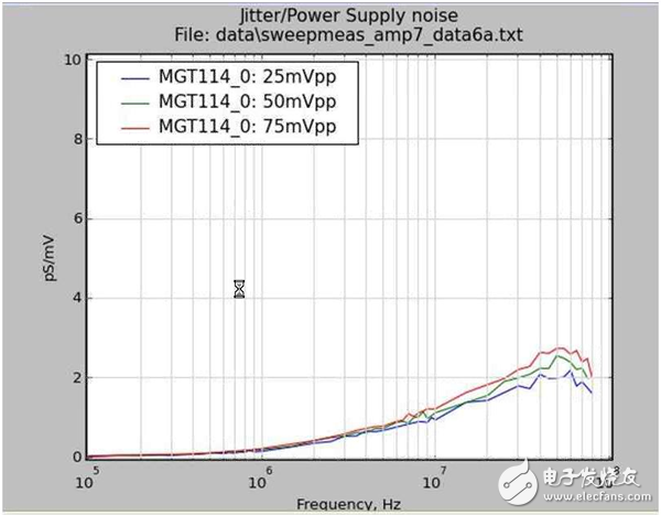
Figure 1 Transfer function curve of power text noise to output Jitter
It can be seen that as the frequency increases, the output Jitter generated per millivolt increases. The sensitivity at 10 MHz is approximately 1.5 pS/mV. Let's take a look at which frequency is the most sensitive to the jitter of the Trender? How much Jitter can be tolerated? According to the characteristics of GTX, RPT120 is reported, and the 10 MHz Jitter is most sensitive to the performance degradation of the CDR (Fig. 2). According to the characteristics of the GTX report RPT120, Jitter deterioration of about 0.1 UI (16pS @6.5Gbps) can be accepted (Fig. 3). At this time, there is only a slight influence on the performance of the CDR.
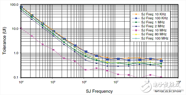
Figure 2. CDR jitter tolerance curve for a 0.4 UI Jitter injected at different frequencies.
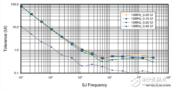
Figure 3. CDR jitter tolerance curves injected into different jitters at 10MHz
However, for power testing, the 10mV pp 10kHz~80Mhz specification is indeed a challenge. The noise floor of many meters (oscilloscopes) may already be close to 5mV. If the probe system does not use a thin coaxial line plus a DC block, the noise introduced from the probe may have exceeded 10mV pp. Therefore, it is necessary to select an oscilloscope with a low noise floor, preferably a filter with adjustable frequency points, and only measure the frequency range of 10 kHz to 80 Mhz. Adjust the vertical resolution of the oscilloscope to 5mV/div and set the horizontal direction to 100uS/div for long afterglow test (see Figure 4). The maximum peak-to-peak value is required to be no more than 10mV. If we find that the maximum peak-to-peak value is less than 10mV, we can use the spectrum analyzer as an additional test to see where the main noise spectrum is (see Figure 5). If it is not on the sensitive frequency (such as 10MHz), but in the low frequency band (such as below 1MHz), the performance of the system will not be greatly affected. It can be left unprocessed because it is costly to process the power supply filter at low frequencies. For example, you need to switch to LDO to increase the system cooling burden.
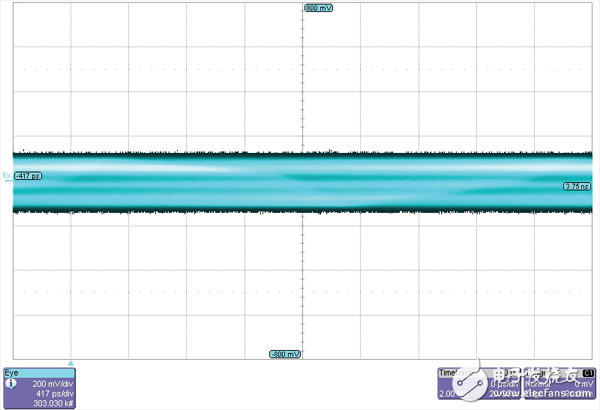
Figure 4 Long afterglow method to test power supply noise
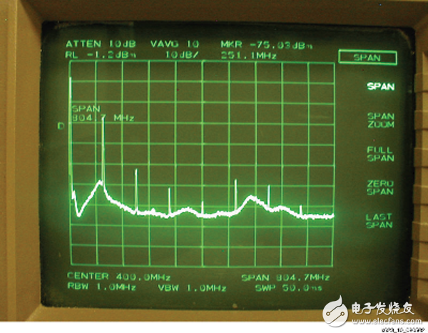
Figure 5 spectrum analyzer test power supply noise spectrum
From the engineering practice of recent years, even if a separate DC/DC module is not used to power the SERDES, it does not cause SERDES problems. Even if the measurement finds a problem, it is a problem that the measurement itself is not introduced in the correct way. Therefore, the requirements for power supply noise caused by XILINX are scientific and reasonable to be realized and verified.
we are ok to provide cable assembly design assistance, rapid in-house prototyping(CAD, SOLIDWORK), manufacturing engineering, tool making, also accept flexible Qty,even including working round-the-clock to meet tight turning-round time requirements.
Our wire harness products are customized for various industry, like automotive, elecrical, mechanical, etc.
<
| Electric harness |
| Date Cable For Communication |
| Radio Frequency Cable and Flat Cable |
| LCD Backlight Display Cable |
| Computer peripheral Cable |
| Stored-program control cable |
| Adapter For Outdoors BillBoard |
| WireHarness For Control System |
| Converter Cable For Tunnel Enery-saving Lamp |
| Wire Harness For ATM |
| Wire Harness For POS Machine |
| Wire Harness For Refilling tankers |
| Main Wiring Harness For Elevator Control |
| Power Cord For Circuit Box |
<
| Wireharness For Game machine |
| Converter Cable For Solar Energy |
Game machine wire assembly, wiring harness for game machine, electrical wiring harness, custom wire harness for game machine
ETOP WIREHARNESS LIMITED , https://www.etopwireharness.com