The SPWM (Sinusoidal Pulse Width Modulation) technique is a well-established method that has gained widespread use in modern power electronics. One of the key insights from sampling control theory is that narrow pulses with equal area but different shapes have similar effects when applied to an inertial system. This principle underpins the SPWM approach, where a pulse waveform is designed to mimic a sine wave. By controlling the on and off states of switching devices in an inverter circuit, the area of the output voltage pulses can be made to match the area of a corresponding sine wave segment. This allows for precise control over the frequency and amplitude of the inverter’s output voltage by adjusting the modulating wave.
**Structure of a Three-Phase SPWM Inverter**
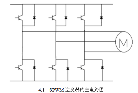
The main circuit of an SPWM inverter is essentially similar to that of a standard PWM inverter. However, instead of using thyristors, the voltage-type PAM configuration typically employs IGBTs (Insulated Gate Bipolar Transistors), which offer faster switching and better efficiency. In SPWM, the voltage switches direction rapidly, but the half-wave remains unidirectional. As a result, the output voltage and current may not always align in direction, necessitating the use of freewheeling diodes to provide a path for reverse current. The basic structure of an SPWM inverter includes a three-phase inverter bridge with anti-parallel diodes connected across each IGBT.
Figure 4.1 illustrates the main circuit of an SPWM inverter, which consists of six IGBTs arranged in a three-phase bridge configuration, each paired with an anti-parallel diode. These components work together to generate the desired output waveform.
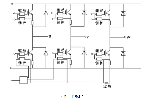
IGBTs require specific drive and protection circuits to function correctly. In practice, they are often integrated into intelligent power modules (IPMs), which include built-in drive and protection features. IPMs also provide overheat protection for the entire module, making them more reliable and easier to implement.
For lower capacity applications, IPMs are commonly designed as multi-cell structures, such as six-cell or seven-cell modules. A six-cell IPM integrates a complete SPWM inverter, while a seven-cell IPM adds components for energy consumption braking. Figure 4.2 shows a typical six-cell IPM, which contains five main circuit terminals: DC positive and negative inputs, and three-phase AC outputs. It also includes several control terminals for driving and protection, allowing direct connection to conventional control chips or optical couplers.
When dealing with larger capacities, integrating the entire inverter into a single IPM can lead to increased size, weight, and cost. Additionally, if one component fails, the entire module must be replaced, raising maintenance costs. To address this, larger systems often use two-unit or single-unit IPMs. A two-unit IPM includes all components of an inverter bridge arm, such as two IGBTs, freewheeling diodes, and their associated drive and protection circuits. A single-unit IPM contains just one IGBT along with its diode, drive, and protection circuitry.
In addition to the main circuit, a snubber circuit is essential to limit the rate of voltage change during switching. This helps reduce electromagnetic interference and protects the IGBTs from damage. The driving circuit, protection circuit, and other auxiliary circuits, including the buffer circuit, are all interconnected to ensure stable and efficient operation.
**Four Key Features of SPWM Inverters**
Although square wave inverters are simple to implement, they suffer from high harmonic distortion, limiting their use to very specific applications. With the introduction of SPWM technology, inverter systems entered a new era, especially with the rise of digital signal processors (DSPs), which enabled more advanced control and smarter operation.
The SPWM inverter has the following distinct characteristics:
1. **Simplified Circuit Design**: The main circuit is similar to that of a square wave inverter, but it allows for adjustable output voltage, frequency, and phase with just one power level.
2. **Independent Power Factor Control**: An uncontrollable rectifier bridge can be used, enabling the system's power factor to remain independent of the inverter's output voltage.
3. **Simultaneous Frequency and Voltage Control**: SPWM allows for both frequency modulation and voltage regulation without relying on the original parameters of the system, and it does not affect the system’s dynamic response.
4. **Low Harmonic Distortion**: SPWM significantly reduces harmonic content, with harmonics distributed symmetrically around the carrier frequency. This makes the output waveform much cleaner and more suitable for sensitive loads.
SPWM stands for Sinusoidal Pulse Width Modulation, a technique that originated from communication modulation methods. The core idea involves using a reference (modulation) wave, typically a sine wave, compared to a triangular carrier wave at a higher frequency. This comparison generates a series of rectangular pulses with widths varying according to the reference wave’s amplitude and frequency. These pulses are then used to control the switching of power devices, producing an output waveform that closely resembles a sine wave. This technique is widely used in modern power conversion systems due to its efficiency, precision, and flexibility.
Auxiliary Equipment For Plastic Recycling Machine
High-Quality Auxiliary Equipment For Plastic Recycling Machine,Customizable Auxiliary Equipment For Plastic Recycling Machine,Advanced Technology In Auxiliary Equipment For Plastic Recycling Machine,Auxiliary Equipment For Plastic Recycling Machine Manufa
Zhejiang IET Intelligent Equipment Manufacturing Co.,Ltd , https://www.ietmachinery.com