**Foreword**
With the rapid development of computer technology, the USB interface has become one of the most essential external expansion interfaces in personal computers. When developing USB peripherals, it is crucial to write firmware that enables communication between the device and the host. This paper presents the development of a USB interface firmware program written in C language using the Keil C51 software environment. The main functions of the firmware are described, along with its flow, structure, and endpoint configuration. Key implementation details are also provided, making the code easy to modify, test, and understand. This approach enhances code readability and ensures the program is versatile and portable across different platforms.
When designing a USB peripheral, developers typically need to create three key components: firmware, USB drivers, and client applications. Once the device is connected to the host via a USB cable, the host detects the new device and establishes a connection. One of the primary goals of writing firmware is to ensure that the operating system, such as Windows, can recognize and identify the device properly. The firmware for the PDIUSBD12 chip was developed in the Keil C51 environment, which is a powerful tool for 8051-based microcontrollers. It offers a wide range of library functions, robust debugging tools, and an intuitive user interface, making it ideal for embedded development. Additionally, the object code generated by Keil C51 is efficient, with compact and readable assembly code, further supporting its use in this project.
**1 Main Work Done by the Firmware Program**
The main objective of the firmware design is to enable seamless data and command transfer between the host and the device, ensuring the PDIUSBD12 achieves maximum USB transfer speed. The firmware is closely tied to hardware, involving tasks like USB device connection, protocol handling, and interrupt management. When the PDIUSBD12 receives a packet from the USB bus, it triggers an interrupt to the CPU. The CPU responds immediately, reads the data from the buffer, sets event flags, and continues executing the main program. The firmware is structured into three parts: initialization of the microcontroller and peripherals, a main loop that can be interrupted, and an interrupt service routine (ISR) that handles USB events.
According to the USB protocol, all data transfers are initiated by the host. Therefore, the microcontroller acts as the foreground process, waiting for interrupts. When the host sends a token packet to the device, the PDIUSBD12 generates an interrupt, triggering the ISR. The firmware then reads the interrupt register to determine the type of token packet and performs the necessary actions. Thus, the core of the firmware lies in the interrupt service routines, which handle various types of USB transactions.
Communication between the MCU and the PDIUSBD12 is achieved through command and data exchanges. The PDIUSBD12 supports three types of commands: initialization, data stream, and general commands. Each command has a specific address and function, allowing the MCU to send or read data accordingly. By organizing each command into a separate function, the code becomes modular, reusable, and easier to maintain.
**2 Firmware Program Flow and Structure**
The USB device startup process involves several steps: connecting the device to the USB port, the host reading the device descriptor twice, loading the appropriate driver based on the vendor and product ID, and initializing the device by reading descriptors and selecting endpoints. During firmware development, the microcontroller’s interrupt should be set to level-triggered mode. After each interrupt, the last transfer status register must be read to clear the interrupt flag, ensuring proper operation of the PDIUSBD12.
The firmware is structured in a layered manner, making it simple to modify, test, and adapt to different platforms. It is based on source code provided by Zhou Ligong MCU, with a hierarchical sub-module design that allows for easy migration by modifying only certain sections of the code. The firmware structure is illustrated in Figure 1, showing the key components such as the hardware abstraction layer, D12 command interface, interrupt service routines, main loop, and protocol layer.
**3 Endpoint Configuration**
The PDIUSBD12 chip features three input/output endpoints, each configurable for different purposes. In this application, the endpoints are configured according to Table 1. Endpoint 1 is used for control commands, receiving two-byte instructions from the host, while Endpoint 2 is responsible for transmitting key signals at a 1 ms interval. These configurations ensure reliable communication between the device and the host.
**4 Firmware Program Implementation**
The firmware uses a multiplexed address/data bus mode, where the least significant bit of the address line determines whether the data is a command or a data byte. The main loop initializes the I/O ports, sets up interrupts, and continuously checks event flags to execute corresponding tasks. This approach ensures smooth operation and real-time response to user inputs.
**5 Conclusion**
This paper presents a well-structured USB firmware program for the PDIUSBD12 chip, developed in the Keil C51 environment. The code is simple, readable, and highly portable, making it suitable for various USB peripheral applications. By following a modular and layered design, the firmware ensures flexibility, ease of modification, and efficient performance.
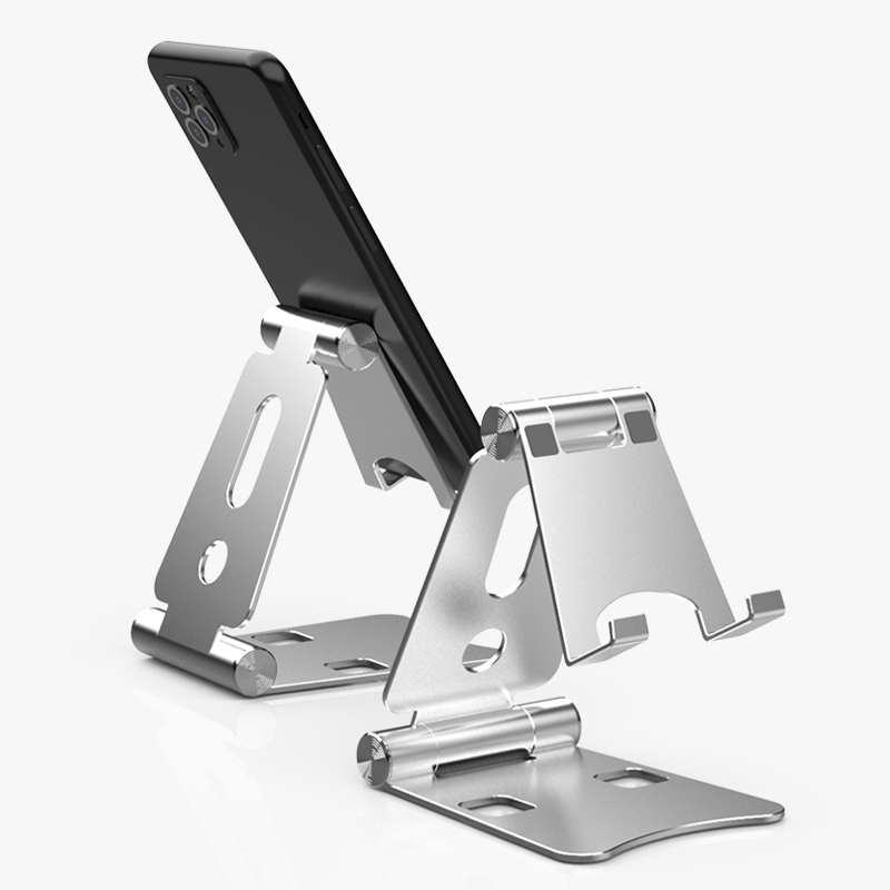
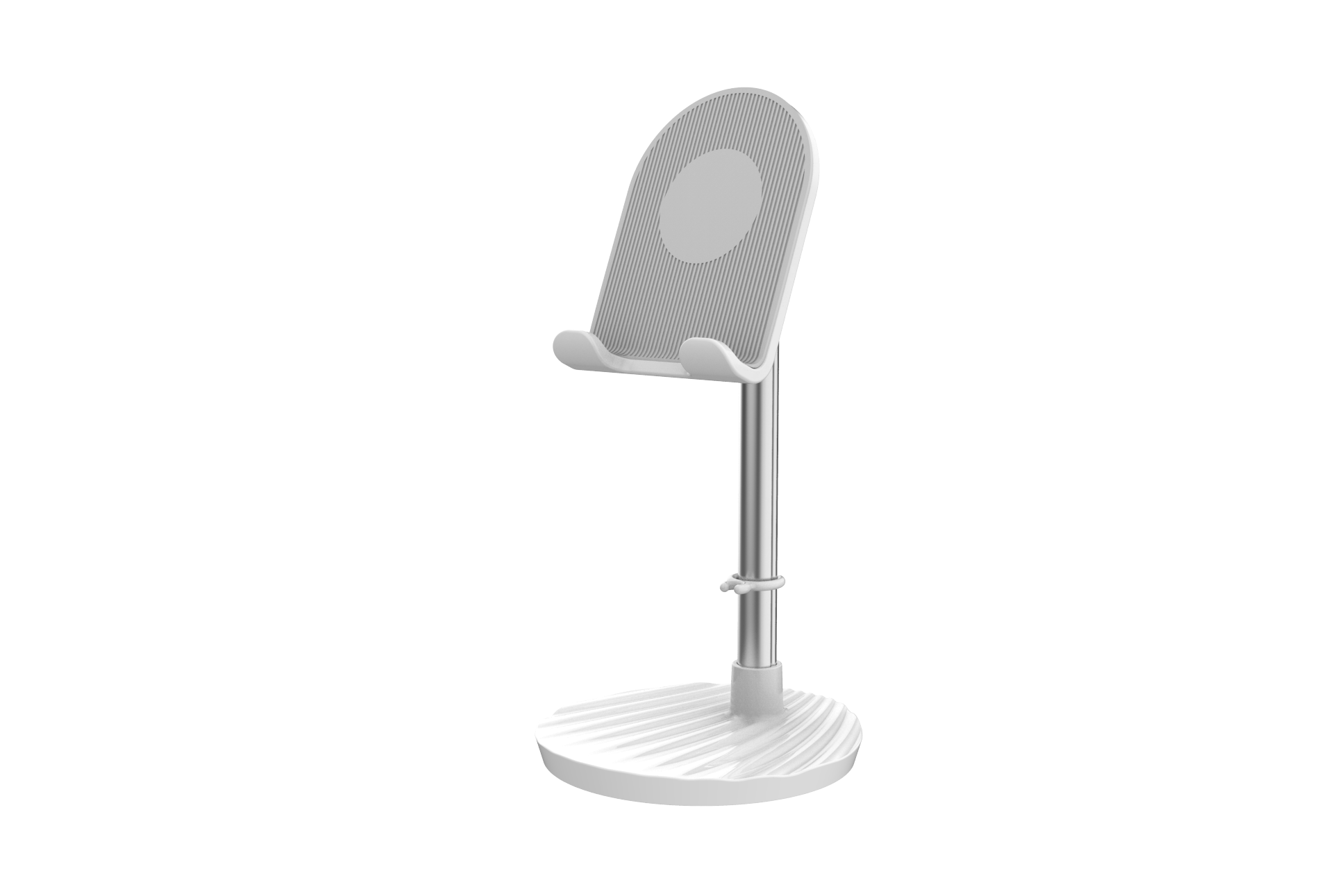
Phone Holder Magent
1. Desktop Mobile Phone Holder; open the Phone Holder directly to 45 degrees, put the phone on it and you can use it
2. The bedside mobile phone holder; fix the clip of the mobile phone holder on the side of the bed, freely adjust the bending degree of the holder and the position of the mobile phone according to your posture, which is convenient and more comfortable.
3. Stick to the wall mobile phone bracket; the bracket sticker has strong adhesiveness and can be fixed and hung on glass, ceramic tiles and painted walls.
4. Car phone holder; car air outlet bracket, fixing method: After the mobile phone is installed on the mobile phone bracket, pop out the steel piece in the middle of the mobile phone bracket and put it into the car air outlet to fix it
5. Ring buckle mobile phone holder, the usage method only needs to stick the suction ring on the back of the phone, and then put the ring out to place the phone.


Phone Holder,Cell Phone Holder,Cell Phone Holder Bed,Cell Phone Holder Desk
Shenzhen ChengRong Technology Co.,Ltd. , https://www.laptopstandsupplier.com

