I. Introduction
The three-phase thyristor bridge type semi-controlled rectifier circuit can control the DC output voltage of the rectifier circuit by changing the control angle of the trigger circuit of the thyristor under the condition that the AC power supply voltage is constant. The circuit is medium-sized. Rectifiers or applications that do not require reversible electric drag systems are more widely used. The traditional three-phase bridge half-controlled rectifier circuit requires three independent analog triggers to trigger the thyristor. Because of the complicated circuit, difficult adjustment and low reliability of the analog trigger, this paper proposes a The digital flip-flop circuit composed of 80C196KC single-chip microcomputer greatly simplifies the control circuit. The generated trigger pulse has the characteristics of wide phase shifting range, high control precision, fast dynamic response, stable and reliable performance, and its performance index is better than analog trigger. .
Second, the circuit composition and principle analysis
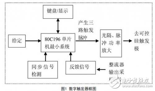
1. The digital flip-flop of the three-phase thyristor half-controlled bridge rectifier circuit is composed of the minimum system of 80C196KC MCU, synchronous detection circuit and pulse power amplifier circuit, as shown in Figure 1. The microcontroller 8 0 C 1 9 6 KC, latch, 27C256 program memory, 62C256 data memory constitutes the minimum system. The 80C196KC is a 16-bit high-performance single-chip microcomputer from Intel Corporation. Its power consumption is extremely low. In addition to normal operation, it can also operate in both standby and power-down modes. Its working speed is several times higher than that of the 51 MCU. The bus width is 8/16 bits optional and the internal width is always 16 bits. 80C196KC contains 8 10-bit A/D converters, 512 bytes of RAM, 2 hardware timers/counters, one monitor tracking timer, and the crystal oscillator is 12MHz. The single-chip microcomputer is formed according to the difference between the given and feedback signals. The phase shift pulse with the control angle α is output from the HS0.0~0.2 pin.
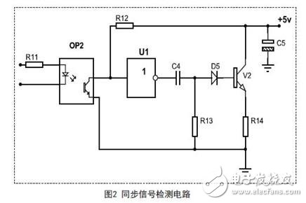
2. Synchronous signal detection consists of opto-isolation, comparator and shaping circuit (Figure 2). When the zero-crossing of the line voltage UAC sent by the synchronous transformer, a square wave is generated at the output of the opto-isolator, which is shaped by the inverter U1 and differentiated by the RC circuit to generate a pulse as an external interrupt signal to the EXTINT end of the 80C196KC. , to achieve the trigger pulse and power synchronization. In order to simplify the circuit, the system adopts a relative trigger mode, which only needs single-phase synchronization.
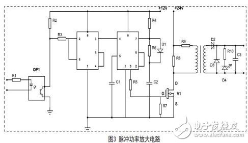
3. Pulse power amplifier circuit. As shown in Figure 3, in order to achieve reliable triggering of large inductive loads, the trigger circuit uses a pulse sequence triggering method. The pulse output from the single-chip port HS0.0~0.2 is sent to the pulse cluster forming circuit consisting of 555. After being amplified by the FET and separated by the pulse transformer, it is output to the trigger pole of the thyristor.
Third, the control angle algorithm
The thyristor control angle α is obtained by the following equation:
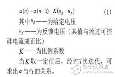
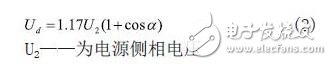
In the case of a large inductive load, the relationship between the output voltage Ud of the three-phase half-controlled bridge rectifier circuit and the control angle α is:
The above equation shows that the output current Id and the control angle α of the three-phase half-controlled bridge rectifier circuit are nonlinear, and the equation (1) is based on linearization, so it must be corrected by the following formula:
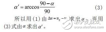
In order to simplify the procedure, the control angle α is obtained by using U to give a -ω-α' lookup table. Since the A/D converter of the MCU is 10 bits, the given voltage of 5V is 3FFH=1023 after A/D conversion. If it is divided into 51 files, then:
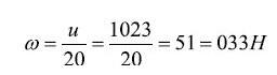
So ω=33H corresponds to the given voltage U=5V; when U=4.9V, the binary number is 1003H, then:
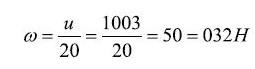
The rest of the analogy, which is exactly 0. 1 V corresponds to 0 1 H, 0.2 V corresponds to 02H, ..., etc., which is convenient for table lookup.
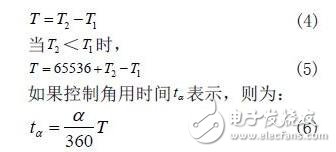
A zero-crossing detection circuit generates a sync pulse at a synchronous voltage UAC from a negative half wave to a positive half-wave zero-crossing. Since the UAC lags behind the phase voltage UA30°, the timing at which the sync pulse occurs is exactly the natural commutation point of the phase A voltage. The natural commutation points of each phase of A, B, and C are 120° different from each other. When the natural commutation point of phase A is found, the natural commutation points of the other B and C phases are different from each other at T/3, T is The second measured voltage period can be obtained by measuring the time interval between two adjacent sync pulses.
Let 2 T and 1 T be the time when the synchronization pulse appears and the time when the last pulse appeared. When 1 T 》 1 T, then:
The software timer is started at the natural commutation point of each phase (the tuning time is αt), and the time when the software timer expires is the timing at which the phase emits a trigger pulse (control angle α).
The phase shift range of the three-phase bridge type semi-controlled rectifier circuit with large inductive load is 0~180°. When the control angle α is greater than 120°, the adjacent two thyristor trigger circuits may work at the same time, so each thyristor must have its own trigger circuit in the analog trigger circuit. Since a single-chip microcomputer can only form a digital trigger circuit, in order to make the three-phase circuit share a trigger circuit, we must limit the control angle α to within 120°. This can be done by changing the triggering order.
When α1 2 0°, VT1 should be triggered at 120°~240°, then VT2 and VT3 should be triggered every 120°, but VT3 can be triggered by α'=α-120° at 0~120°, over 120°. Later, VT is triggered by α'. 1. Obviously the two are equivalent, but after this processing, the control angle can be limited to 120°, and a flip-flop can be shared.
PZDK series of automatic constant current charge and discharge equipments are specially designed for the battery charging and discharging applied in railway. They are used for the maintenance and capacity verification of storage battery used in locomotive, railway vehicle and generator car, which can improve the service life of the battery and ensure the safe running of locomotives and other railway vehicles.
The main control unit of the equipment is PLC and the HMI (Human Machine Interface) is 7" LCD colorful touch screen. The equipment has varieties of operating modes, and can automatically record and save working status.

Battery Charging And Discharging Equipment
Railway Battery Charger,Charging And Discharging Device,Battery Charge Discharge Device,Electric Pallet Truck Battery Charger
Xinxiang Taihang Jiaxin Electric Tech Co., Ltd , https://www.chargers.be