Abstract: Based on the consideration of improving the CAN bus networking capability, a novel CAN repeater design method is proposed; the hardware design scheme with the LPC2119 controller as the core is described; the software implementation process under the μC / OSII real-time operating system is analyzed in detail For the real-time and safety of the repeater and the possible speed mismatch between the bus and the bus, establish an improved method to improve the priority of emergency tasks, establish relevant event signs, and reasonably synchronize events and tasks. So as to effectively solve the problem of limiting the longest transmission distance and the maximum number of power saving in the network.
Keywords: Repeater CAN LPC2119 μC / OSII
Introduction
The direct communication distance of the CAN bus is only about 10 km, and due to the limitation of the driving ability of the transceiver, only 110 nodes can be hung on the bus at most, which brings certain difficulties to the system networking. The CAN repeater is designed to solve this problem. Set the initialization parameters of the CAN repeater, you can use different communication rates in different network segments, and you can also filter the messages to reduce the burden on the bus.
1 Hardware design of CAN repeater
1.1 Introduction to the microcontroller LPC2119
CAN repeater is a hardware and software system based on ARM microcontroller LPC2119. LPC2119 is a 16 / 32-bit ARM7TDMISMCU produced by Philips that supports real-time simulation and tracking, with 128 KB embedded high-speed Flash memory. The unique acceleration structure enables 32-bit code to run at the maximum clock rate. Applications with strict code size control can use the 16-bit Thumb mode to reduce the code size by more than 30%, but the performance loss is very small. Two CAN controllers are integrated inside the LPC2119. Its main features are: data transfer rate up to 1 Mb / s on a single bus; 32-bit register and RAM access; compatible with CAN 2.0B, ISO 118981 specifications; global acceptance filter can recognize all 11-bit and 29-bit Rx logos The acceptance filter provides Full CANstyle automatic reception for the selected standard identifier.
1.2 Comparison between LPC2119 internal CAN controller and SJA1000
The CAN controller integrated in the LPC2119 is roughly the same as the Philips SJA1000 CAN controller, but it is slightly different in the acceptance filtering loop, which provides convenience for developers who are used to SJA1000 to adopt the LPC2119. The SJA1000 acceptance filter is defined by the acceptance code register and the acceptance mask register. The bit pattern of the received message is defined in the acceptance code register. The corresponding acceptance mask register allows certain bits to be defined as "irrelevant". Different modes can be selected through the mode register Filter mode: single filter mode and double filter mode. For the CAN controller integrated inside the LPC2119, the global acceptance filter includes a 512 & TImes; 32 (2 KB) RAM, which can be stored in the RAM with 1 to 5 identifier tables through software processing. The entire RAM can accommodate 1024 standards The identifier or the extended identifier of 512 or a mixture of two types of identifiers. At the same time, there are 5 address registers pointing to the acceptance filter RAM table: Full CAN standard address, standard single address, standard address range, extended single address or extended address range. When the receiving end of the CAN controller has received a complete identifier, it will notify the acceptance filter, the acceptance filter responds to this signal, and reads out the controller number, identifier size, and the identifier from the controller itself , And then search the table in RAM through the acceptance filter to decide whether to receive or discard this frame of information.
1.3 CAN repeater hardware structure
The block diagram of the hardware structure of the repeater is shown in Figure 1. The LPC2119 is connected to two buses via CAN bus transceiver; the bus driver is powered by an isolated DC / DC module, which not only realizes the electrical isolation between the two CAN interfaces, but also implements the repeater and CAN bus electrical appliances. isolation. In addition, there are LED display and keyboard interface. The LED is used to display the working status of the repeater, and the keyboard is used to modify the baud rate of the bus. The debugging and tracking of the final program is done through the JTAG debugging port.
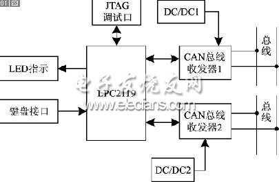
Figure 1 hardware structure block diagram
2 System software design
2.1 Introduction of μC / OSII real-time operating system
As applications become more complex, using traditional front-end and back-end design methods will become too complicated, real-time performance is not guaranteed, and deadlocks are prone to occur. The best way to solve these problems is to use a real-time operating system.
μC / OSII is a preemptive real-time kernel, which is based on priority, that is, the task with the highest priority in the ready state is always run first, so the real-time performance is better than the non-preemptive kernel. It contains real-time kernel, task management, time management, communication synchronization between tasks (semaphore, mailbox, message queue) and memory management; most of its code is written in C language, which is highly portable and can Runs on most 8-bit, 16-bit, 32-bit, and even 64-bit microprocessors, microcontrollers, and digital signal processors (DSPs).
CAN repeaters have relatively high requirements on the real-time and reliability of the system. Using μC / OSII real-time operating system can effectively schedule tasks; assigning different priorities to each task can ensure timely response of tasks, and using real-time operating system reduces the complexity of the program and facilitates program development.
2.2 Issues to be considered in software design
(1) Capacity of use code
In the design of front / backend systems, the demand for memory capacity depends only on the application code, while the use of RTOS is very different. The RTOS kernel itself requires additional code space.
Total code size = application code + kernel code
Each task runs independently, and a separate stack space (RAM) must be provided for each task. When deciding how much stack space to allocate to each task, it should be as close to the actual demand as possible. The size of the stack space not only needs to calculate the needs of the task itself (local variables, function calls, etc.), but also needs to calculate the maximum number of interrupt nesting levels (save registers, local variables in the interrupt service program, etc.). Another feature that the kernel should have is that the amount of stack space required for each task can be defined separately. All cores require additional stack space to ensure internal variables, data structures, queues, etc. If the kernel supports stack separation for interrupts, the expression of the total RAM requirement is: total RAM requirement = application RAM requirement + kernel data area RAM requirement + sum of each task stack requirement + maximum interrupt nested stack requirement.
Unless there is a particularly large amount of RAM space available, special care must be taken when allocating and using the stack. Real-time multitasking systems require more code (ROM) and data space (RAM) than front-end and back-end systems. The extra code space depends on the size of the kernel, and the amount of RAM depends on the number of tasks in the system.
(2) Real-time and security
The CAN repeater is one of the key devices for system networking. Repeaters are often used in the slightly larger CAN bus system. It not only brings convenience to system networking, but also adds some store-and-forward delays to the system. Therefore, the real-time nature of the system must be considered in software design to minimize the data store-and-forward time. In addition to assigning higher priority to system data forwarding tasks, a communication mechanism should be established to ensure that when data on one bus is received, it can be sent to another bus immediately. In addition, the repeater is the communication bridge between the two buses. In order to ensure the normal communication between the two buses, try to avoid situations like deadlock and bus failure. Therefore, the system must design a monitoring task that can respond to such situations in real time. At the same time, in order not to lose the data that has not been forwarded, a ring buffer must be set for each bus to store the newly received data and maintain the system. safety.
2.3 System design and implementation
The embedded CAN repeater mainly realizes the mutual forwarding of data between two CAN buses, and can change the baud rate of a certain CAN controller according to actual needs. Using μC / OSII real-time operating system, the entire design consists of the operating system and a series of user applications.
The main function is the first function executed by the program. This function will never return, mainly to initialize the system hardware and operating system. The hardware includes initializations such as interrupts, keyboards, and displays; the operating system includes task control and event control fast initialization, and at least one task must be created before starting multitask scheduling. A startup task is created in this system, which is mainly responsible for the initialization and startup of the clock, the startup of the interruption, the initialization and startup of the CAN controller and the division of tasks. After handing over the CPU usage rights, only do some idle processing.
(1) Division of tasks
To complete the various functions of real-time multitasking, the tasks must be divided. This program divides the program into six tasks with different priorities according to the importance and real-time nature of each task, including system monitoring, data forwarding, keyboard input, LED display, receiving queue monitoring, and baud rate setting. Table 1 is the task division table.
In addition to the six main application tasks, there are two interrupt service subroutines: a clock tick interrupt, which is used to provide a periodic signal source; and a CAN receive interrupt, which is used to write the received data into the ring buffer.
.jpg)
Owl Clock Moving Eyes,Gear Moving Clock,Cat Clock With Moving Tail,Horse Clock
Guangzhou Huanyu Clocking Technologies Co., Ltd. , https://www.findclock.com