More and more companies are beginning to use variable speed drive engines to reduce energy consumption. This requires simplifying the design by moving from a differential (PID) controller to a fuzzy logic-based system, reducing development time and eliminating complex mathematical formulas.
This article refers to the address: http://
However, this poses new challenges to the engine. The use of conventional integral and derivative (PID) controllers to control the speed of brushless direct current (BLDC) motors is complex because they rely on complex mathematical models and are computationally intensive. The algorithm using Fuzzy Logic (FL) can eliminate the dependence of the design process on complex mathematical formulas and provide an easy to understand solution. Another advantage of fuzzy logic (FL) engine control over (PID) differential controllers is that the development cycle is shorter. This paper discusses the process of using the Texas Instruments c28xx fixed-point DSP series to implement a fuzzy logic algorithm to control a brushless DC motor.
Development of Brushless DC Motor Control Model
Before the fuzzy logic (FL) engine is built, we must first build a model as the basis for the design. Fuzzy logic controllers use heuristic knowledge and use a language description model to express its design. We will start with a PID controller model instead of developing a model from scratch. Once development and implementation is complete, the fuzzy logic controller will improve performance by adjusting its parameters.
In general, there are three design steps for developing a fuzzy logic brushless DC controller:
1. Define the operating range of the input and output controllers.
2. Define the functions and rules of a fuzzy member set.
3. Adjust the engine.
The first step is to define the mode-dependent inputs and outputs. The input is the error (E), which is the current error between the set speed (SS) and the current speed (CS); the other input is the change in error (CE), which is the current error and the previous calculation error (PE) The difference between. The output is the change in armature voltage (CV), which is the difference between the existing armature voltage (CAV) and the previous armature voltage (PAV) saved value. The resulting model equation is as follows:
E=SS-CS
CE=E-PE
CV=CAV-PAV
The unit of engine rotation speed is revolutions per minute (RPM), and E determines the extent to which the target speed is approached. Therefore, when E>0, the rotational speed of the engine is lower than the set speed; when E<0, the motor rotational speed exceeds the set speed. The CE determines the direction in which the controller is adjusted. CE is positive if and only if (iv) the current rotational speed is lower than the set speed; CE is negative if and only if the current rotational speed is greater than the set speed. When approaching the set speed, the CE will adjust back and forth between positive and negative values. The CV is the supply voltage of the armature. This voltage is expressed as the pulse width modulation (PWM) duty cycle.
The next step is to define the member functions, variables, and rules of the fuzzy set. In order to be able to work, non-blurred (clear) inputs and outputs must be transformed into ambiguous. Conversion uses the use of language variables to represent the input and output ranges. These are also known as fuzzy variables. A fuzzy variable is used to divide the area of ​​membership values ​​for member functions. For example, five variables are used to map inputs and outputs, which are medium negative (NM), small negative (NS), zero (z), small positive (PS), and medium positive (PM).
It is not a mathematical formula, the fuzzy controller uses fuzzy rules to make decisions and produces an output. Fuzzy rules are described in the form of IF-THEN statements. Fuzzy rules determine the behavior of the system, not complex mathematical equations. For example, if the error (E) is equal to a medium negative value (NM) and the error change (CE) is equal to a small positive value (PS), then the change in the armature voltage (CV) is equal to the small negative value (NS). Some of the rules used are based on the designer's experience and system knowledge. Therefore, the number of rules used by our system is 25.
In order to activate the armature, the CV fuzzy output must be converted back to a clear output. This process is called defuzzification. A popular deblurring method is called the center of gravity method.
The final step in the design is to adjust the member functions and rules. This phase is also known as the optimization adjustment phase. Optimized adjustments are used to improve the performance of the fuzzy controller. Once the design is complete, the controller is ready to be implemented.
The implementation of the fuzzy logic controller is composed of three modules. They are fuzzification, rule deployment, and defuzzification. The following sections discuss the implementation of fuzzy logic brushless DC motor related modules.
Fuzzy
Fuzzification is the process of converting data with a clear value into fuzzy data. The resulting fuzzy data conversion is based on the fuzzy membership of the input variables. For this application, the motor control input variables are the rotation error (Error) and the rotation error difference (Cerror). The rotation error (Error) is the absolute rotational speed difference from one sampling time to the next. Similarly, the rotational error difference (Cerror) is the value of the rotational error change between one sampling time and the next. The formula is as follows:
Rotation Error (Error) = SetSpeed ​​(Current Speed) - Cur-rentSpeed
Rotation error difference (Cerror) = rotation error (Error) - Pre-viousError (previous error)
As mentioned earlier, five member sets are defined for the rotation error (Error) variable and the rotation error difference (Cerror) variable:
1. NM: medium negative
2. NS: small negative value
3. ZE: zero
4. PS: small positive value
5. PM: medium positive value
Figure 1 shows the five member sets defined for the rotation error (Error) variable and the rotation error difference (Cerror) variable. These member sets are triangular overlaps to provide a good response. Each group has a maximum value of 0 x 1 AAA.
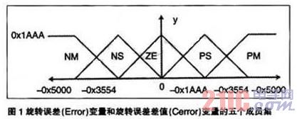
The input variable is blurred to produce a five-part vector that corresponds to the medium negative, small negative, zero, small positive, and medium positive values ​​of the fuzzy member set. The value of the Y-axis corresponding to each component represents the membership of the explicit input value. The vector contains the rotation error (Error) and the rotation error difference (Cerror). The fuzzification values ​​are represented as arrays x1[] and X2[].
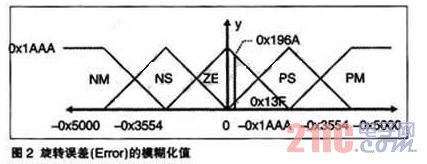
Figures 2 and 3 graphically show the rotation error [Error] and the rotation error difference (Cerror) fuzzification value.
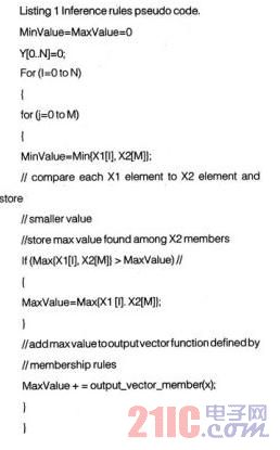
Fuzzy inference rule
Fuzzy inference rules determine the behavior of a system by manipulating fuzzified data. Specifically, the obfuscated data is applied against the rule table. In terms of language, this is the comparison of the input data Error, Cerror and the rules table. The rule table contains the member sets NM, NS, ZE, PS, and PM, and operates according to the control plane. The output is a valid "inferred" or "established" rule. The description of the reasoning process can be found in the following pseudocode list:
Defuzzification
Defuzzification is the process of converting fuzzy data into clear data. For this application purpose, the defuzzified value determines the duty cycle of the PWM signal used to drive the motor. The duty cycle depends on the use of the modified centroid calculation function. The deblurring method used here is to multiply a coefficient by a centroid calculation function. The modified calculation is also called the centroid point calculation function. The calculation formula for the centroid point is:
Defuzzified VaLue=∑-Y[i]XmultCoeff[l]/∑Y[i]
Where i of i[i] is the output vector element, which is the coefficient by which the output member set of multCoeff[i] should be multiplied. Among them, i can take 1 to 5. The result of the formula calculation is the result of defuzzification.
Figure 4 graphically shows the output member set used by the application and the [-0x10, -0x8, 0x0, 0x8, 0x10] coefficients.
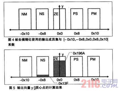
Assuming that y[]=[0x0,0x13F, 0x196A, 0x0, 0x0], the deblur output values ​​are as follows:
Defuz=0×(-16)+319×(-8)+6506×(0)+0×(8)+0×(16)/0+319+6506+0+0=-2552/6825=“ -0.37391
Figure 5 shows the calculation results for the output vector y[] centroid point.
Hardware description
The eZDSP2812 board is used in this motor control application. The core of the eZdsp board is the TMS320F2812 digital signal processor. The board uses the timer T1, 20 kHz clock to generate the PWM 1-6 signal and uses the timer T2 to execute the Interrupt Service Routine (ISR). In addition, the input capture pin CAP1-3 is used to collect high-speed data from the Hall effect sensor.
The engine is driven by a PWM signal generated by the DSP. These six PWM signals are used as the source of the three-phase power converter. The power converter converts these six signals into three-phase signals and directly acts as the power source for the engine. The function of the three-phase power converter is handled by an auxiliary motor control board. The spectrum number provides two boards that provide this capability: the DMC550 and the DMC1500. Any one of them can be directly inserted into the eZdsp28xx board.
Hall effect sensors are used for fuzzy logic control loop feedback. The conversion of the three-phase power converter switch is determined by detecting the signal received from the Hall effect sensor. This signal is sent to the acquisition pin of the TMS320F2812. The actual motor speed is calculated by a software module.
Software introduction
The motor control software consists of a digital microcircuit (DMC) library module and an FL motor control program. Seven modules in the Digital Microcircuit (DMC) library are used in this application. They are:
·Datalog data record ·BLDC3PWM
·tall3_Drv
·Mod6_Cnt
·Rmp2Cntl
·Rarnp_Cntl
·Speed_PR
In addition, fuzzy logic engine control is handled by a main FuzzyCtl() routine; for brushless DC motors, Fuzzy-BLDC().
The software first performs the first run configuration and then the application-specific settings. Specifically, the GPIO pins are configured as CAPture and PWM pins.
The next step is to initialize the timer and module parameters, as well as the ISR settings. When all peripheral settings are completed, the interrupt is activated and enters the main control system. The main control system calls the fuzzy controller every 8.7 milliseconds.
The error value is converted into a fuzzy value by blurring and stored in X1[] and X2[]. Once converted, the fuzzy values ​​are applied to the fuzzy inference rules.
The results obtained from the inference module are stored in Y[]. The output from Y[] is converted to a clear value in the defuzzification module. The resulting sharp value is a PWM offset that is added to the current PWM duty cycle. The updated PWM value is checked to see if the new value is within a certain range, and if not, appropriate action will be taken. Finally, the fuzzy controller returns the updated PWM duty cycle to the calling routine.
Figure 6 shows the demo application debugging.
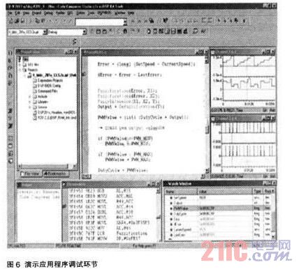
Channels 1 and 2 (shown in the upper right corner) show the PWM counter and the capture Hall effect sensor, respectively. Channels 3 and 4 (below channels 1 and 2) show the version of the edge-triggered PWM counter and the Hall effect sensor display window. Important variables are displayed in the watch window, the most important of which are SetSpeed ​​and CurrentSpeed. These values ​​are close enough that the output of the fuzzy logic controller is zero.
This session shows that the engine is operating under no load conditions. This behavior may be slightly different from the situation when there is a load. In addition, if you want a finer granularity, it may be necessary to adjust the controller.
XLPE insulated electrical Power Cable consists of below major components: one or more high quality stranded copper or aluminum conducts, XLPE insulation, fixed tape and filler, optional protective armour, overall PVC sheath.
These cables are with simple structure, light weight and high heat resistance. With the development of our technology, our factory is able to manufacturing our products more lighter, durable and flexible for international requirements.
It could be classified into 3 type as below:
Non-armoured XLPE Power Cable(Cu or Al /XLPE/PVC)
Steel Tape Armoured Power Cable(Cu or Al/XLPE/STA/PVC)
Steel Wire Armoured Power Cable(Cu or Al/XLPE/STA/PVC)

Manufacture Standard
This cable is manufactured according to the standard of GB12706-2008(The Same as IEC60502).It can also be manufactured according to IEC,BS,UL as request.
Using features
l Max. permissible continuous operating temperature of conductor is 90℃.
l Max. temperature of conductor during short circuit (5s maximum duration ) shall not exceed 250℃.
l The ambient temperature under installation should not below 0℃.
l The bending radius of a single-core cable: not less than 20
times of cable`s OD
The bending radius of a three-core cable: not less
than 15 times of cable`s OD

Why choose XLPE Insulated Power Cable?
l Heat resistant performance-With XLPE special structure, it will not be decomposed and carbonized up to 300℃ with at most 40 years life time.
l Insulating Performance-Same insulation characteristic as PE, higher electrical resistance and less impact by temperature.
l Mechanical Performance-Higher hardness, stiffness, abrasion resistance and shock resistance.
l Chemical performance-XLPE has higher resistance to acid and alkaline. It only produce water and carbon dioxide, it shows more environmental friendly which could satisfy modern requirements of fire safety.
Application:
This product is suitable for transmission and distribution of electrical power with AC rated voltage 0.6/1Kv,1.8/3 kV,3.6/6 kV,6/10 kV,8.7/10 kV,8.7/15 kV,12/20 kV,26/35kV kV. Such as power distributing systems, industrial plant and others.
You are always welcome to contact us if you have any questions about XLPE electrical power cables. We will offer you professional solutions as you required with attractive price.
XLPE Insulated PVC Sheathed Power Cable
XLPE Insulated PVC Sheathed Power Cable,Power Cable With XLPE Insulator,XLPE Insulation Power Cable,XLPE Insulated Power Cable
Fujian Lien Technology Co.,Ltd , http://www.liencable.com