MEMS accelerometers have been used for collision and shock detection in automotive airbag applications for more than a decade. Currently, MEMS accelerometers have become part of automotive safety systems. An example of a system is Electronic Stability Control (ESC), which detects accidental skidding during cornering and automates engine, suspension, and braking to stabilize the vehicle. Due to US requirements, by 2015, all light vehicles will be equipped with ESC, so MEMS accelerometers will be more widely used in the automotive industry.
This article refers to the address: http://
Accelerometers used in safety systems require high sensitivity, high accuracy, high reliability, and match the communication interface of the ESC system. Since the acceleration at side slip is less than 1 g, the accelerometer must be very sensitive to sense low gravity movement. The inductive response must also track acceleration with a high signal-to-noise ratio (S/N) and low offset error over the operating temperature range. Accelerometers must be robust and reliable so that their structure does not break or damage under the high pressure of the automotive environment, and the device should return to normal operation immediately after an overload. In addition, the digital codec output must be able to be processed directly by other devices within the ESC system.
The following discussion describes an accurate and reliable accelerometer based on Freescale Semiconductor's High Aspect Ratio Micro Electro Mechanical Systems (HARMEMS) technology, which can be used in advanced ESC systems.
Variable volume accelerometer
The principle of operation of the variable volume accelerometer is very easy to understand. Figure 1 shows a simple model of a capacitive accelerometer. The intermediate movable element is supported by a spring between the fixed elements. From an electrical point of view, it is equivalent to two back-to-back capacitors with varying capacities. When the acceleration is 0, the middle plate remains in the middle position, and the upper and lower gaps do not change. Therefore, the capacitance peak (Ct) is balanced with the capacitance valley (Cb).
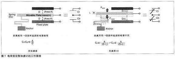
When the sensor accelerates, the movable element is forced to move by the kinetic energy (Faocel) from Newton's equation. At the same time, the spring is bent by the moving element, and according to Hooke's law, a restoring force (Frestore) is generated in the reverse direction. Therefore, the movable plate will eventually move to a position where the spring restoring force and the acceleration force are balanced (Frestore=Faccel). At this point, the capacitor gap is changed and the capacitance is also changed. The change in capacitance will be converted into an electrical signal, which we can determine by measuring the electrical signal.
Capacitive accelerometers have other advantages, such as low power consumption, no drive current, and easy to match CMOS circuits. For automotive applications, the biggest advantage is that the capacitive accelerometer can be tested by moving the movable component through the electrostatic force generated by the fixed plate. This is called a self-test feature. The self-test electrode's bias is added to the acceleration on the sensor and does not produce actual acceleration. It is useful to verify the mechanical integrity of the sensor's operational integrity before activating the system. Self-testing is a necessary feature for life support applications such as airbags.
SiP solution with sensor chip and ASIC chip
The actual accelerometer products include sensor chips and signal processing chips (A-SIC), which are packaged in system package (SiP) technology. The sensor chip is fabricated using MEMS technology. The ASIC chip contains signal conditioning and other features and is fabricated using CMOS technology. Process separation allows for maximum utilization and productivity of each technology. In addition, SiP assembly solutions can drive faster time to market because of the MEMS technology combined with various standard or professional CMOS, SMOS, BiCMOS technologies (depending on the application). The flexibility to manufacture a wide range of specific products is achieved without the need for system-on-a-chip (SoC) integration.
Improvements in MEMS sensors and improvements in ASIC signal processing and compensation have affected the accuracy and reliability of automotive accelerometers, which we will discuss later.
MEMS sensor improvement
MEMS accelerometers for automotive applications must achieve high sensitivity, overdamped mechanical response, and adhesion failure prevention.
1. Sensitivity enhancement
The sensitivity of the MEMS accelerometer itself is defined by the mechanical parameter movable component mass (m) and spring constant (Ks). The principle of operation is: when the acceleration moves, the middle plate moves a long distance, and the differential capacitance changes more, thereby achieving high sensitivity. The moving distance (L) depends on the balance between the acceleration force (Faccel=m×a) and the spring restoring force (Frestore=Ks×L), that is, the greater the mass that the midplane can withstand, the greater the acceleration force, and the movement The longer the distance. On the other hand, a soft spring with a small spring constant requires more bending to achieve a balanced restoring force. In the sensor structure design, a heavier midplane or soft spring can be used to create a highly sensitive accelerometer that can move a longer distance even at very low accelerations (<1g).
Interestingly, although the gap change is the main factor determining the acceleration, the absolute capacitance change is based on the initial capacitance (C0). The rate of change of the differential capacitance does not depend on the value of C0. However, for the first stage of the capacitor (the voltage converter circuit on the ASIC chip), it is desirable to have a larger absolute capacitance change because it helps to improve the signal to noise ratio in the background noise. Capacitor board area expansion increases initial capacitance while also increasing midplane quality. Therefore, the high sensitivity of the car accelerometer can be achieved by increasing the quality and area of ​​the midplane.
2. Overdamped response
The accelerometer response feature is derived from the instantaneous movement of the midplane. As already explained in the principle of operation, the middle plate is moved to a position where the spring restoring force and the acceleration force are balanced (Frestore=FacceI). As the midplane moves, it gets resistance from the surrounding atmosphere. This movement is usually interpreted as a damped oscillation.
![]()
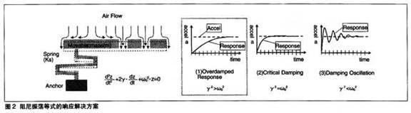
Damping oscillations can be explained by other terms. The first term is the acceleration of the board when moving (not the acceleration from the outside). The second term is the drag effect when the board moves into the atmosphere, and y is a drag factor from air viscosity, friction, board area, and other functions. The third term is the spring restoring force effect, which is the natural frequency of the system.
There are three solutions to the damped oscillation equation (see Figure 2). For automotive applications, if the required response time has been obtained, the overdamped response with a drag effect greater than the spring effect (y2 > w02) is ideal.
![]()
It converges to the equilibrium position without oscillation and looks like a mechanical low-pass filter. The overdamped sensor mechanically cuts off the high frequency noise component and increases the signal to noise ratio (S/N) on the output signal. In this way, the original acceleration signal can be read correctly.
The overdamped mechanical response of an automotive accelerometer can be achieved by expanding the movable plate to obtain more air resistance, consistent with the sensitivity increase method discussed above.
3. Overtravel stop and adhesion prevention
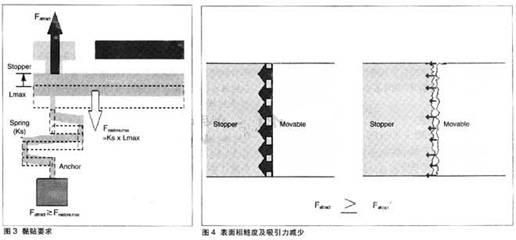
The movable midplane in the capacitive accelerometer must be stopped before the board is in contact with the fixed plate. There is also a fixed structure that stops the midplane, called the overtravel stop (or stop). The first function of the stopper is to prevent the capacitor from being short-circuited. The second effect is to reduce the spring's strength due to fatigue by defining a range of curvature in the lower side of the proportional region of Hooke's law. The third function is to prevent the movable plate and the fixed plate from sticking. Adhesion is carried out by the attraction between the contact faces. When the contact surface is wide, the plates may not be separated because the total attractive force is too large, and when the contact area is small, the attraction is weak, so the plates can be easily separated.
However, in practical applications, even a small-sized stopper will stick after the movable plate is stopped, which is called in-use pasting. It is a more serious failure mode that temporarily or permanently disables the sensor. Therefore, in-vehicle adhesion must be prevented in automotive safety applications. The expression that produces the paste is as follows:
![]()
That is, the attraction of the contact surface of the stopper is greater than the maximum restoring force of the spring (see Figure 3).
To prevent in-use adhesion, the opposite of the above equation must be achieved by increasing the spring restoring force or reducing the planar attraction of the stopper. However, in highly sensitive automotive sensors, the spring constant should not be excessively increased because the spring constant is an important factor in determining the sensitivity of the accelerometer. However, even if the spring is hard, the sensitivity can be improved by increasing the quality of the middle plate. In the sensor structure design, the plate quality and spring constant must be adjusted.
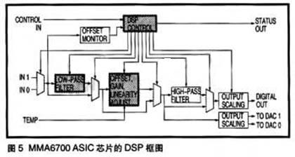
On the other hand, the attraction can be reduced by roughening the stop plane, since this reduces the effective contact area of ​​the midplane contact stop, so the total attractive force of the stopper is reduced (see Figure 4). In addition, the hydrophobic coating on the sensor structure can also reduce the gravitational component on the plane.
4. HARMEMS technology
Freescale's HARMEMS (High Aspect Ratio MEMS) technology is a MEMS process technology used to fabricate highly sensitive, highly reliable automotive accelerometers. HARMEMS allows the lateral sensor for detecting acceleration to be parallel to the surface of the chip, and the single crystal silicon having a thickness of 25 μm is the substrate of the SOI wafer (insulated silicon wafer). The 25um thickness material allows for the high flexibility of low acceleration sensors with heavier movable components. Also, since the 25um thick plate experiences considerable air resistance while moving, an overdamped mechanical response is achieved.
To prevent in-use sticking, heavier movable components can have a hard spring that creates a strong restoring force while reducing the attractiveness of the stopper. The HARMEMS roughened scalloped sidewall surface structure is created by a deep RIE (Reactive Ion Etching) process. The roughened surface reduces the effective contact area of ​​the stopper, thus reducing the attractiveness and reducing the incidence of sticking. The HARMEMS accelerometer demonstrates accurate, reliable technology to automotive safety driving support systems.
ASIC circuit improvement
ASIC circuits for automotive ESC applications must have a wide dynamic range with high signal-to-noise ratio, low gain/bias error at different temperatures, and digital communication.
1. Wide dynamic range and high signal to noise ratio
The MEMS accelerometer output for ESC applications should have a wide dynamic range (full size/minimum signal), ie greater than 60 dB. By comparing MEMS sensor signals with driver inputs such as driving, acceleration and brake combinations, the ESC system can detect any change in vehicle performance. These effects may vary over a very wide range. On the other hand, even a small input or signal can affect car performance. Therefore, MEMS accelerometers must detect small changes in behavior, and ASIC circuits must be able to identify and process small signals throughout the operating range.
When an ASIC input stage circuit (an analog amplifier) ​​is used with a MEMS sensor, the noise generated internally must be reduced. Minimizing the analog circuitry helps limit the noise generated by the noise source. In addition, according to the Slgma-Delta (∑△) modulation noise shaping effect, the ∑Δ conversion that occurs after the input of the analog circuit can reduce the noise component in the low frequency region. The high over-sarnpling frequency of the ∑Δ conversion improves the detection resolution, and the signal-to-noise ratio and dynamic range are thus improved. Therefore, by reducing the noise of the minimum analog input circuit and improving the detection resolution of the ∑Δ converter, a wide dynamic range can be obtained.
2. Small gain/bias error
The ESC system also requires an offset accuracy of ±100 mg (now ±75 mg) over its operating temperature range. Any inherent offset error can result in incorrect position readings of changes in vehicle behavior. Also, bias changes due to temperature changes will result in larger errors.
The sensor is designed to minimize the effects of overtemperature bias changes. To further reduce misreading, the ASIC chip should include initial adjustment of gain and offset. This adjustment is made around the sensor within the required specifications. In addition, the ASIC chip features temperature compensation for gain and bias. The temperature sensor can be integrated on a chip, such as a P-type polysilicon resistor and an N-type Well resistor in a CMOS process. For some points within the operating temperature range, the adjustment code is stored on the on-chip non-volatile memory during the test. In the actual operation, it is necessary to refer to the correct adjustment code and compensate the actual temperature. Therefore, the gain/bias adjustment error over the entire temperature range can be reduced by means of the temperature sensor's adjustment and compensation functions and the non-volatile memory on the ASIC chip.
3. Digital communication function
The ESC system requires an additional communication interface and digital codec data from the sensor. That is, the accelerometer must include an analog-to-digital (A/D) converter and a digital communication interface circuit on the ASIC chip. The analog to digital conversion is performed by a ∑Δ converter and a subsequent analog input circuit. The output is a pulse-width modulated serial digital data stream that is virtually immune to external noise. The digital data stream can be provided to a digital signal processor (DSP), which uses a more sophisticated filtering function than the analog circuits currently on the market to improve the accuracy of the signal information.
The digital data is transmitted using the communication interface of the ESC system, and the car-specific communication bus preferably uses the serial peripheral interface (SPI). On the serial interface bus, the ESC system and sensors are defined as master-slave relationships, and many slave devices can be connected to the bus. These bus systems, such as DSI or PS15, also reduce the amount of wiring, thereby reducing the attenuation of communication signals (even digital signals). Therefore, the digital communication interface is realized by a ∑Δ converter, a DSP, and a serial communication interface circuit on the ASIC chip.
ESC system low gravity accelerometer products
Freescale Semiconductor's MMA6700EG is an exemplary accelerometer that meets all the requirements of an ESC system. The MMA6700EG uses HARMEMS technology and includes an XY-axis sensor. The ASIC also has the following features:
·Overdamped mechanical response
Wide range of dynamic range (±3.5g FS, 11-bit resolution, 66dB)
High signal to noise ratio (greater than 68 dB)
·Gain/offset adjustment function
· Only ±75mg offset error over the entire life cycle and temperature range
· Bidirectional self-test and calibration · Serial Peripheral Interface (SPI)
· Integrated DSP low pass filter
Some of the features of the MMA6700 are discussed below.
1. Sigma Delta (∑△) converter
Two ∑Δ converters are independently connected between the X/Y axis MEMS sensor and the DSP circuit. The ∑Δ converter provides a pulse width modulated data stream and samples the DSP at 1 MHz. In the output portion of the ∑Δ converter, there is dynamic gain control. When the smaller signals are inconsistent, the input gain is larger, and when the larger signals are inconsistent, the input gain is smaller. Therefore, the dynamic range is expanded to a high resolution of more than 11 bits.
2. Regulation and low pass filter
The DSP included in the MMA6700 has two functions. One is temperature/compensation for gain/offset adjustment and the other is low-pass filter. The functional block diagram of DSP is shown in Figure 5. The MMA6700 is capable of adjusting the detectable acceleration range, ±3.5g or ±5g, to create different products on the final test line. Also in the final test line, the gain/bias error is measured over the highest and lowest operating temperature ranges and these compensation codes are saved. In practical applications, the output is compensated by an on-chip temperature sensor (TEMP). Therefore, the output bias error is controlled within ±75 mg over the entire operating temperature range.
In addition, the cutoff frequency of the low pass filter function (8.8 Hz to 884 Hz) can be programmed on the final test line according to each customer's specifications. The low pass filter removes high frequency noise components from the output, which increases the signal to noise ratio.
3. other functions
The MMA6700 also features a HOLD function that measures acceleration at the synchronization timing of the ESC system. The bidirectional self-test is controlled via the SPI interface and verifies the operational integrity of the sensor mechanically and electrically without any actual acceleration.
summary
This article discusses automotive accelerometer requirements for electronic stability control (ESC) systems. Based on Freescale Semiconductor accelerometer products using HARMEMS technology, the paper introduces the technologies and improvements. More than just accelerometers, any device used in an ESC system must be developed with a system-level partner. These system-level partners manufacture fail-safe microcontrollers, brake system modules and their integrated software.
The Shackle Insulator is made from high quality porcelain material, The Porcelain Shackle Insulator can endure high amount of temperature and current, Shackle Type Insulator usually used in low voltage distribution network.Such High Voltage Porcelain Shackle Insulator can be used either in a horizontal position or in a vertical position. Shackle insulator can be directly fixed to the pole with a bolt or to the Cross Arm .
Features
1.The tapered hole of the spool insulator distributes the load more evenly2.Minimizing the possibility of breakage when heavily loaded
3.Very reliable, with a proven track record. Over 80 years of experience
4.Easier to maintain, can be coated and washed
5.Easy to identify a damaged unit
The following shackle insulators comply with the BS standard, the glaze colour of the insulators are brown, light gray etc..
| MAIN DIMENSIONS AND STANDARD PARTICULARS | |||
| Type | ED-2(B) | ED-2(C) | |
| Main Dimensions | H | 76 | 80 |
| D | 89 | 80 | |
| d | 48 | 50 | |
| d1 | 21 | 22 | |
| R | 10 | 6 | |
| Transverse Stength,KN | 12.7 | 13.2 | |
| Power Frequence Flashover Voltage | Dry,KV | 25 | 25 |
| Wet,KV | 12 | 12 | |
| Net Weight, Each Approx., kg | 0.5 | 0.5 | |
")
")
We warmly welcome friends both domestic and abroad to visit our company, if you have any questions, please contact with us directly.
Shackle Insulator
Shackle Insulator,Shackle Type Insulator,Porcelain Shackle Insulator,High Voltage Porcelain Shackle Insulator
FUZHOU SINGREE IMP.& EXP.CO.,LTD. , https://www.cninsulators.com