Abstract: This paper reviews the development and basic structure of hybrid electric vehicles. On the basis of this, combined with Toyota Motor Corporation's latest generation hybrid electric vehicle Prius THS II, the specific application of power electronics technology in hybrid electric vehicles is introduced. . Finally, combined with the actual situation of hybrid electric vehicles, the problems that need to be solved are put forward. This article refers to the address: http:// Keywords: electric car  Hybrid  Power electronics  AC drive  Inverter 1,  introduction Power electronics technology is a discipline that studies power semiconductor devices to achieve power conversion and control. It is an emerging discipline in which electronic, power semiconductor devices and control cross each other. It studies a wide range of topics, including power semiconductor devices, magnetic materials, power electronics circuits, control integrated circuits, and power conversion devices. At present, the main directions of power electronics research are: (1)       Design, testing, model analysis, process and simulation of power semiconductor devices; (2)       Circuit topology, modeling, simulation, control and application of power switching converters; (3)       Power inverter technology and its application in industrial fields such as electric drive and power system. As a clean, efficient and sustainable means of transportation, electric vehicles ( EVs ) are of great significance for improving air quality and protecting the environment, and provide solutions to the increasingly serious oil charter. At the same time, electric vehicles are used as power electronics technology. A new application area, covering all transformations of DC/DC and DC/AC , is a very practical application area. 2,  Hybrid Electric Vehicle Introduction At present, the world automobile industry is in the development stage of technological revolution and industrial adjustment. Safety, environmental protection, energy conservation and intelligence have become major issues of common concern in the automotive industry. In order to sustain the development of human society and the automotive industry, countries around the world, especially developed countries and some developing countries, are studying new technologies to improve the coordination of automobiles and the environment. As the main direction of the transformation and development of the automobile industry in the 21st century, electric vehicles have now transitioned from the experimental development test phase to the commercial trial production stage. Many well-known automobile manufacturers in the world have introduced high-tech safety or environmental protection model cars. The purpose is to guide the trend of the world's automotive technology. 2.1 Characteristics and development of various types of electric vehicles Depending on the power source used, the electric vehicle can be roughly divided into three categories: storage wave electric vehicles or pure electric vehicles (Battery Electric Vehicle), to a hydrogen-powered fuel cell electric vehicle (Fuel Cell Electric Vehicle) and hybrid electric automotive (Hybrid Electric Vehicle). Pure electric vehicles are powered by batteries alone, but the performance and price of power batteries have not yet made a major breakthrough. Therefore, the development of pure electric vehicles has not achieved the intended purpose; Fuel cell electric vehicles have unparalleled advantages such as high energy conversion rate, no pollution to the environment, and long service life. However, due to the current breakthrough in fuel cell technology and research, the development of fuel cell electric vehicles has also been limited. Hybrid electric vehicles use electric motors and engines as their power units. The advanced control system enables the two power units to work together to achieve optimal energy distribution, achieving new vehicles with low energy consumption, low pollution and high automation. Since 1995 , the world's major automakers have shifted their research focus to the research and development of hybrid electric vehicles. Large auto companies in Japan, the US and Germany have developed hybrids including cars, vans and trucks. electric car. For example, Toyota Motor Corporation, which is the frontier of hybrid electric vehicle research and development, has developed a hybrid electric vehicle that has reached a practical level. Since the launch of the world’s first mass-produced hybrid electric vehicle Prius in 1997 , its Later, in 2002 , the hybrid van was introduced. The hybrid power system of the car adopts the electric multi-wheel drive and four-wheel drive / braking force integrated control system that was first mass-produced in the century . In 2003 , Toyota introduced a new generation of Prius , also known as the “New Age Toyota Hybrid System – THS II†(see Figure 1 ). The energy saving effect can reach 100km and the fuel consumption is less than 3L . Since 2004 , Toyota has introduced a new Lexus RX luxury hybrid sedan to the European market . Toyota plans to use gasoline-electric hybrid engines in 2012 to improve fuel economy and reduce emissions. 2.2 Hybrid electric vehicle classification and characteristics According to different combinations of engine and motor, hybrid electric vehicles can be divided into three categories: series, parallel and hybrid. The basic structure is shown in Figure 2 . Figure 3 shows the power distribution of the motor and engine in different hybrid types: In a series hybrid system, a generator is driven by an engine to drive the wheels by an electric motor using the emitted electrical energy. That is, all the kinetic energy emitted by the engine must first be converted into electrical energy, and the electric energy is used to drive the vehicle. The parallel hybrid system uses the engine and the electric motor to drive the wheels. The two power sources are used according to the situation. Since the power sources are parallel, they are called parallel hybrid systems. The hybrid type is also called series-parallel type, which can maximize the advantages of both series and parallel. This is how the Toyota Prius series hybrid system works. In operation, the power splitter is used to distribute the power of the engine: on the one hand, the wheels are directly driven, and on the other hand, the power generation is controlled autonomously. Since the electric motor is driven by electric energy, the usage ratio of the electric motor is increased as compared with the parallel type. |

3, Â HEV commonly used power electronics technology and devices
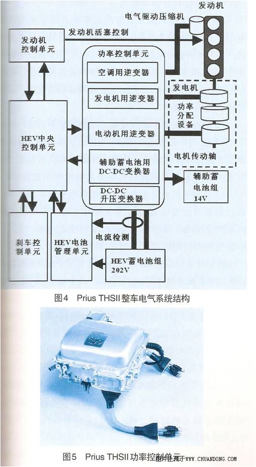
This paper combines Toyota's new generation hybrid system THS II to specifically study the application of power electronic technology in HEV . THS II's complete vehicle electrical drive system (see Figure 4 ) mainly uses AtkinSon Circulating high-efficiency engine, permanent magnet AC synchronous motor, generator, power splitter , high-performance nickel metal hydride ( NI - MH ) battery, control management unit, and DC - DC converter of each related inverter .
High-voltage power supply circuits, various inverters, and auxiliary DC-DC converters for 14V batteries form a power control unit (see Figure 5 ) that integrates DSP controllers, drive and protection circuits, DC stabilized capacitors, and semiconductors. Insulators, sensors, liquid cooling circuits, and CAN bus interfaces to automotive communications .
3.1 Motor / generator inverter unit
In Prius  In the THS II main drive system, the three-phase voltage inverters (powers of 50 kW and 30 kW , respectively) for motors and generators are integrated into one module (as shown in Figure 6 , the electrical structure of the inverter is shown in Figure 7) . Show), the maximum supply voltage of the DC bus is set to 500V . IGBT devices use a commercial power with antiparallel freewheeling diode (850V / 200A), the power level of the IGBT having a sufficient capacity to withstand the maximum back pressure of 500V, and other such avalanche breakdown, the instantaneous short circuit capacity.

Each bridge arm of the motor inverter is composed of two IGBT modules and a diode module in parallel . Area of each IGBT chip is 133mm 2 (13.7mm × 9.7mm), and an emitter using 5 μ m thick aluminum; the area of each diode chip is 90mm 2 (8.2mm × 11mm).
At present, electric vehicles generally adopt PWM- controlled voltage-type inverters. This inverter has the characteristics of simple circuit and high efficiency, and the PWM inverter exhibits the following development trends:
(1) Â Â Â Â Â Â Usually IGBT devices are used , the operating frequency is high, and the low-frequency harmonic components and the current shock of the starting are reduced. The highest switching frequency of current foreign applications has reached 20 kHz ;
(2) Â Â Â Â Â Â The rated frequency of the motor is correspondingly increased, and the speed regulation range is expanded to reduce the volume and weight of the motor and improve the power ratio while better meeting the operation requirements. At present, the highest rated frequency of foreign electric motor-specific motors has reached 500Hz ;
(3) Â Â Â Â Â Â Computer control system of the DSP is capable of reliable operation and a vector control, the motor starting torque can be achieved quickly and weakening Constant speed operation, such a control system is stable, a small current pulse, high efficiency control.
In addition to the above traditional PWM control technology, a resonant DC link converter and a high frequency resonant AC link converter have recently appeared. Resonant converters with zero-voltage or zero-current switching technology have the advantages of low switching loss, low electromagnetic interference, low noise, high power density and high reliability, which have attracted wide interest of researchers.
The commonly used electronic switching devices currently used in power converters mainly include GTO , BJT , MOSFET , IGBT and MCT . Due to the combination of IGBT set BJT and MOSFET , the high- impedance voltage-controlled gate can significantly reduce the gate drive. The power can be integrated into the gate drive circuit; and the IGBT has a very short switching time, which enables the system to have fast response, reduces switching losses, and reduces noise, so the IGBT is a good switching device. MCT is also a potential choice device, although the current commercial MCT rating has yet to be improved; but because MCT has a low voltage drop, so with the new MCT manufacturing process and the use of new materials, the future MCT is There will be good application prospects in electric vehicles.
3.2DC — DC Boost Converter Unit
In THS , the battery is directly connected to the motor and generator through the inverter (see Figure 8 ); in THS II, the voltage output from the battery pack is first boosted by the DC - DC boost converter, and then reversed. variable is connected, and the bus voltage of the inverter from the original THS is now promoted to 220V 500V.
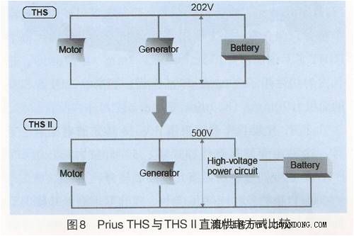
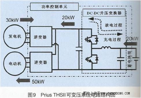
Figure 9 is a schematic diagram of energy exchange in the THS II system. The power of the generator in Figure 9 is 30 kW , and the instantaneous power of the battery pack is 20 kW . The two combine to provide energy for the 50 kW motor. The capacity of the boost converter in Figure 9 is also Designed to be 20kW .
This system has the following advantages:
(1) Â Â Â Â Â Â Since the maximum output power capability of the motor is proportional to the DC bus voltage, compared with the 202V power supply condition of the original THS system, the maximum current of the motor in the THS II system is 500V when the drive current is not increased . The output power and torque output capacity is 2.5 times that of the original THS system ; in addition, the same volume of motor can also avoid outputting higher power;
(2) Â Â Â Â Â Â Thanks to the DC bus supply voltage variable system, THS II can freely adjust the DC bus supply voltage according to the actual needs of the motor and generator, thus selecting the optimal supply voltage to reduce inverter switching losses and motor copper. The purpose of energy saving;
(3) Â Â Â Â Â Â For a battery pack with a constant supply voltage, since the actual output of the motor and the generator can be satisfied by adjusting the output voltage of the step-up transformer, the number of batteries can be reduced to a certain extent, and the whole is reduced. Car quality.
Shown in FIG. 9 DC - DC boost converters are connected in parallel each branch has two IGBT modules and freewheeling diode modules, each IGBT chip area is 255mm 2 (15mm × 15mm), each freewheeling diode The chip has an area of 117 mm 2 ( 13 mm × 9 mm ). The circuit topology shown in FIG. 9 can ensure the instantaneous conversion of the charging and discharging of the battery without interrupting the normal operation of the system. Since the DC - DC boost converter act simultaneously, the system voltage (System Voltage) across the main capacitor is different from the output voltage of the battery pack, a motor and a generator in order to ensure a high operating voltage, low voltage battery without Limitation of output capabilities.
3.3DC - DC Buck Converter Unit
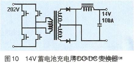
Usually, various electric equipment in the car is powered by a 14V battery pack (rated voltage is 12V ), and the Prius also uses a 14V battery pack as a power supply for controlling on-board electrical equipment such as computers, lights, brakes, etc., and charging the battery. The operation is completed by DC 220V through a DC - DC buck converter. The circuit diagram of the converter is shown in Figure 10 . The converter has a capacity of 1.4kW (100A/14V) , and the power device uses a voltage-controlled commercial MOSFET (500V/20A) . Each MOSFET chip has an area of 49mm 2 ( 7mm × 7mm ).
3.4 Inverter unit for other AC equipment
The Prius THS II air conditioning system uses a motor-driven air compressor to replace the traditional air compressor driven by the engine. In order to drive the motor for the air compressor, a small power inverter ( DC202V , 1.6kW ) was designed . Commercial devices use power IGBT (600V / 30A) with anti-parallel freewheeling diode, wherein an area of each IGBT chip 22.1mm 2 (4.7mm × 4.7mm), the area of each freewheeling diode chip is 9mm 2 ( 3mm × 3mm ) .
4HEV requirements for power electronics technology
Limited by the actual operating conditions, power electronic technology and devices for hybrid electric vehicles are required to have the characteristics of low cost, small size, large specific power, and easy installation. In addition, the following technical details need to be considered:
(1) Â Â Â Â Â Â Power electronic device sealing problem
Various automotive power electronics must be effectively sealed to withstand the effects of temperature and vibration and to prevent the ingress of various automotive fluids.
(2) Â Â Â Â Â Â Electromagnetic compatibility / electromagnetic interference ( EMC / EMI ) problem
Hybrid electric vehicle is a relatively small space, which contains various control chips and weak current circuits. Therefore, in the design of on-board power electronic devices, in order to eliminate future accidents, it is necessary to study and solve EMC/EMI. problem.
(3) Â Â Â Â Â Â DC bus voltage utilization problem
The voltage of a hybrid electric vehicle energy storage system is variable. The magnitude of the voltage depends on the actual load of the vehicle, the operating conditions (electric or power generation), and whether the motor is weakly magnetically operated. The typical bus voltage fluctuation range is the standard. The value is -30%~+25% . Therefore, how to make full use of the DC bus voltage in the case of frequent changes in vehicle operating conditions has become a problem that the control strategy designer needs to solve.
(4) Â Â Â Â Â Â Power electronics control problem
“High switching frequency†and “high sampling rate†are currently widely used in power electronic devices and AC drive systems for hybrid electric vehicles. Objectively “double high†requires high-precision encoders and solvers, so this means How to reduce the parameter sensitivity to meet the control requirements when there is a wide temperature gradient and saturation in the motor.
5 Conclusion
This paper combines Toyota Motor Corporation's latest generation hybrid electric vehicle Prius THS II, summarizes the application of power electronics technology in hybrid electric vehicles, and puts forward technical issues that need to be considered and solved.
With the development of power electronics technology, microelectronic technology and control technology, digital AC drive systems are widely used in commercial electric vehicles. The development of hybrid electric vehicles using AC motor drive systems has been sustainable in the automotive industry. One of the important ways. With the improvement of human requirements for the living environment, the rational use of energy awareness has increased. As a modern vehicle with little pollution and high efficiency, hybrid electric vehicles will have a comprehensive development and application.
DALI Dimmable LED Driver,use DALI system to adjust the light,Private mould non-waterproof IP20 plastic housing series, Square and round types,CE/ROHS/SAA/ETL/TUV/EMC,Input voltage can be both 110V and 220V,Wattage can be 1-80W, Perfect dimming curve, PF>0.95,5%-100% dimming range,constant current 350mA 700mA 900mA 1200mA,constant voltage 12V 24V 36V, parameters can be customization,OEM/ODM is supported,Same appearances but different sizes, forming a perfect product line,Use for led panel light,led strip light and other indoor led lights
Plastic DALI Dimmable LED Driver
700Ma LED Driver,36W Round LED Driver,Round DALI Dimmable Driver,36V DALI Dimmable LED Driver,DALI Dimmable LED Driver,Constant Current DALI LED Driver,DALI Dimmable LED Driver
HAURUI LIGHTING CO.,LTD , http://www.huaruileddriver.com