As the number of vehicles on the road continues to rise, traditional traffic light systems rely heavily on fixed timing control. However, this method is not adaptive to real-time changes in traffic flow. When no vehicles are detected, the opposite direction has to wait until the current green light cycle ends, leading to unnecessary delays and potential congestion. This inefficiency highlights the need for an improved traffic signal control system that can dynamically respond to traffic conditions.
In this paper, we present a smart traffic light control system based on the AT89C52 microcontroller. The system is designed to automatically detect and prioritize emergency vehicles such as ambulances (120) and fire trucks (119) using an infrared receiver. Additionally, it uses vehicle detection circuits to monitor traffic flow and adjust signal timings accordingly. The system also includes LED digital displays for countdowns, manual time settings, forced passage options, and alarm functions for abnormal situations, making it more efficient and responsive to real-world traffic demands.
1. Overall Block Diagram and Working Principle of the Traffic Control SystemThe traffic light control system is built around the AT89C52 microcontroller, which manages the signal lights and controls the LED countdown display. To enhance functionality, the system integrates a violation detection circuit and a traffic flow detection module. These components collect real-time data and send it to the microcontroller, which processes the information and adjusts the signal timing accordingly. A buzzer is also included to alert drivers of violations or emergencies. The overall block diagram of the system is illustrated in Figure 1.
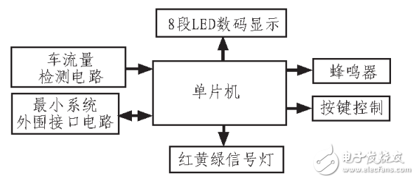
Figure 1: Overall Block Diagram of the System
2. Hardware Structure and Operational MechanismThe system is built using the AT89C52 microcontroller as the central processing unit, along with peripheral components such as LEDs for signal indication, a vehicle detection sensor, a violation detection circuit, and a buzzer for alerts. The hardware design includes a vehicle flow detection circuit, a status light module, an LED countdown display, and input buttons for manual settings. The overall hardware layout is shown in Figure 2.
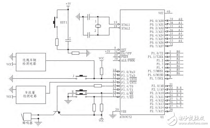
Figure 2: Overall Hardware Circuit Diagram
The microcontroller communicates with various modules through its I/O ports. For example, P0 and P2 are used to drive the LED digital displays, while P1 controls the red, green, and yellow signal lights. The XTAL1 and XTAL2 pins connect to the crystal oscillator, and the RESET pin is linked to the reset circuit. External interrupts (INT0 and INT1) are used to handle emergency signals and traffic detection inputs. The system is programmed to detect vehicle movement and adjust signal times dynamically, ensuring smoother traffic flow.
When the system starts, it waits for user input via mode selection buttons. Users can choose between automatic mode or manual time setting. Once set, the system begins controlling the traffic lights and displaying countdowns. It continuously monitors the traffic flow and adjusts the signal timing accordingly. If an emergency vehicle is detected, the system prioritizes it by activating the buzzer and temporarily halting other traffic flows.
3. Key Control Modules 3.1 Vehicle Detection ModuleThis system employs video-based traffic flow detection. A virtual detection line is set within each lane in the video frame, and image processing techniques are used to capture vehicle movement. The working principle of this detection method is illustrated in Figure 3, while Figure 4 shows the actual video image detection setup.
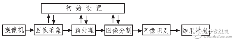
Figure 3: Working Principle of Video-Based Traffic Flow Detection
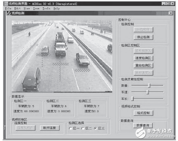
Figure 4: Video Image Detection Map
Gaming Desktop Computer Graphics Card,New RX5500xt 8GB Video Graphics Card,CENTAUR Original New Graphics Card
Boluo Xurong Electronics Co., Ltd. , https://www.greenleaf-pc.com