The number of vehicles on the road is continuously increasing, and current traffic lights rely on a fixed timing control system. However, since traffic flow fluctuates constantly, when no vehicles are detected, the opposite direction must wait until the green light in its own direction ends before it can proceed. This leads to inefficient use of time and often results in traffic congestion in the opposite lane. To address this issue of large-scale traffic jams at urban intersections, it is essential to upgrade the existing traffic light control systems.
In this paper, we present a smart traffic light control system based on the AT89C52 microcontroller. The system is designed to automatically respond to emergency vehicles such as fire trucks (119) and ambulances (120) by receiving infrared signals. It also uses a vehicle detection circuit to monitor traffic conditions and dynamically adjust the duration of green lights based on real-time data. Additionally, an LED digital display shows the remaining time for each signal, enhancing driver awareness and reducing confusion.
Beyond basic traffic control, the system includes manual time settings, countdown displays, forced passage options, traffic flow monitoring, and handling of abnormal situations. These features make the system more adaptable and efficient in managing complex urban traffic scenarios.
**1. Overall Block Diagram and Principle of the Traffic Control System**
The traffic light control system is built around the AT89C52 microcontroller, which directly controls the signal lights and manages the LED countdown display. The system also incorporates a violation detection circuit and a traffic flow detection module to gather real-time data. A buzzer is connected to alert drivers of violations or emergencies.
The overall system architecture includes input modules such as traffic flow detection, violation detection, and user buttons, while output modules include the signal lights, LED display, and buzzer. The block diagram of the system is shown in Figure 1.
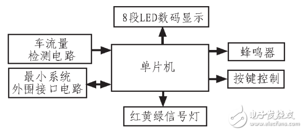
**Figure 1: Overall block diagram of the system**
**2. System Hardware Structure and Working Principle**
The system is built using the AT89C52 microcontroller as the central control unit, forming the core of the minimum system. It is connected to 12 LEDs divided into four groups representing red, green, and yellow lights. Eight additional LEDs are used for countdown displays in both north-south directions. Vehicle flow sensors collect traffic data, while light sensors detect violations. Buttons allow users to set times and select modes, and a buzzer provides audio alerts.
The hardware consists of the microcontroller, vehicle flow detection circuit, violation detection circuit, status lights, LED display, buttons, and a voice prompter. The general hardware design is illustrated in Figure 2.
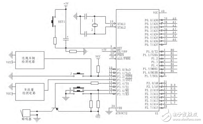
**Figure 2: Overall design circuit diagram**
The P0 and P2 ports drive the LED digital tubes, while P1 controls the color lights. XTAL1 and XTAL2 connect to the crystal oscillator, and the RESET pin connects to the reset circuit. P3.3 is connected to the violation detection circuit, and P3.2 serves as the interrupt for time setting. P0.6 and P0.7 interface with the traffic detection circuit, and P3.6 and P3.7 are used for mode selection and emergency functions. P3.4 is connected to the buzzer.
After power-on or reset, the system waits for the mode selection button to be pressed. There are two modes: automatic and manual. Pressing F activates the automatic mode, while pressing S enters the time-setting mode. Multiple presses of S allow setting different timings for each direction, and pressing F confirms the settings.
Next, the system displays the status lights and LED countdown. It sends status codes to P1 and time values to P0, using P2 to scan the LED display. A 50ms cycle is used to count 1 second, and once that is reached, the time value is decremented and the display is updated.
When the time runs out, the system checks the next state, loads the corresponding code and time, and enables two external interrupts. One handles illegal signals or stop violations, triggering the buzzer and halting all traffic. The other detects vehicles and updates the traffic counter. These features ensure the system remains responsive and adaptive to real-world conditions.
**3. Each Control Module**
**3.1 Vehicle Detection Module**
This system employs video-based traffic flow detection. The idea is to define a virtual detection line in each lane within the video frame, process the image, and capture vehicle information. The working principle and detection diagram are shown in Figures 3 and 4 respectively.
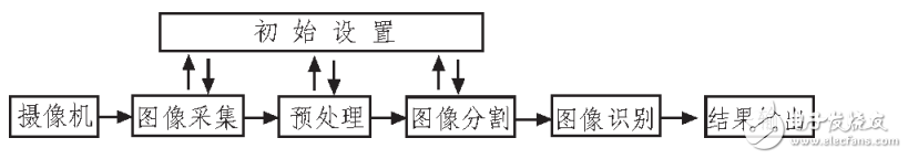
**Figure 3: Working principle of traffic flow detection based on video image**
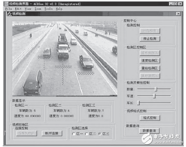
**Figure 4: Traffic image detection map based on video image**
Redundant Power Supply Series,Full Modular Redundant Power,800W Redundant Power Supplies,Redundant Server Power Supply 2000W
Boluo Xurong Electronics Co., Ltd. , https://www.greenleaf-pc.com