Hybrid and electric drive systems used in cars, trucks and motorcycles have created new and previously unknown challenges in the transportation industry. The original 12V voltage network is now complemented by a 400V or higher battery and power system, which sets new requirements for automotive OEM and system module suppliers. Isolation requirements are proposed for all functions in hybrid/electric vehicles such as high voltage batteries, DC/DC converters, inverters for driving motors, and on-board charger modules connected to the 230V/380V grid.
This article refers to the address: http://
Automotive and transportation applications have different requirements for isolation than industrial applications. Solid and reliable is of course necessary, and magnetic "noise" must also have strong resistance. The high power level in the car (such as a 100 kW motor operating at 400 V, meaning 250 A operating current) will generate a strong magnetic field in the car that must be properly handled. The parts used must be long enough to meet the life expectancy requirements of the vehicle; for example, must meet the decades of use requirements for large-scale transportation applications. Products for the automotive environment will drive the quality of automotive applications (Q1) and operate over the -40 to +125 °C operating temperature range.
At the same time, cost pressures in these areas will drive higher system integration requirements, so single-chip products with isolation, such as CAN transceivers, ADCs or gate drivers, offer advantages.
Different digital isolation techniques
In principle, there are four different methods of digital isolation: optical, inductive, capacitive and RF. The first three methods are described below.
Optical isolation technology uses a transparent insulating isolation layer for optical transmission to achieve optical isolation. By driving LEDs (light-emitting diodes), digital signals are converted from electricity to light. The optical signal is then transmitted through the isolation layer, and the optical signal is converted back to the electrical signal by an optical detection component (photodiode, phototransistor).
The main advantage of optical isolation is that light is immune to electric or magnetic fields and has the potential to deliver static signals. At the flipside of the isolation layer, the operating frequency (transmission speed) of the optical isolator is limited by the relatively slow nature of the LED. For hybrid/electric vehicle applications, the limited lifetime of optical isolation is a major drawback. Over time, the efficiency of the LED will decrease, requiring a larger signal drive current (usually starting at 10 mA), so this optical isolation will not function as time goes by.
Inductive isolation uses a change in the magnetic field between the two coils to enable communication across the isolation barrier. One advantage of the inductive isolation method is the difference between common mode and differential transmission, which means that it has good noise immunity. The disadvantage of this approach is that it can be due to distortion of the magnetic field, which is common for motor control environments in hybrid/electric vehicle applications.
Capacitive isolation utilizes the electric field variation across the isolation barrier. The benefits of capacitive isolation are greater immunity to magnetic fields and longer system life. Capacitive isolation is similar to the transmission speed of the inductive isolation method.
However, the disadvantage of capacitive isolation is that there is no differential signal (ie, the signal and noise share the same channel). In addition, as with the inductive isolation method, they cannot directly transmit static signals (which must be encoded with the frequency signal first).
Isolation product
An example of a capacitive isolation method is the ISOxxxx series from Texas Instruments. Figure 2 is a simplified architecture diagram of the ISO72xx system. The ISOxxxx component integrates two bare crystals placed on separate leadframes, as well as transmit and receive chips, in a single package. The two bare crystals are connected by only one bonding wire. The actual isolation function implemented on the receiver is based on silicon dioxide (SiO2, glass) with copper and doped silicon as the substrate electrode capacitor (Figure 3). The use of SiO2 offers the advantages of high reliability and long life.
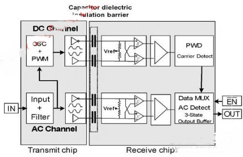
Figure: TI's ISO 72xx series architecture diagram.

Figure: TI's ISO72xx series of dies, with the silicon dioxide isolation on the receiver chip on the right.
Front Door Locks,Sliding Door Lock,Security Door Locks,Bedroom Door Lock
YONGFA INTELLIGENT TECHNOLOGY SECURITY CO., LTD. , http://www.yongfa-safe.com