introduction
As the demand for high-power, low-voltage intrinsically safe power supplies increases, the basic intrinsically safe Buck converter needs to further increase the output power. However, if you want to increase the output power and increase the output current, you can increase the capacity of the inductor and capacitor at the output of the converter. However, it is easy to ignite the explosive gas and reduce the intrinsic safety performance. In addition, you can improve the switching frequency. It can reduce the value of inductance and capacitance required to meet the output ripple voltage requirement, so it is also beneficial to intrinsic safety. On the other hand, increasing the switching frequency reduces the efficiency of the converter, resulting in an increase in the maximum inductor current. Intrinsically safe. In addition, increasing the switching frequency may also cause the actual effective capacity of the capacitor to drop significantly, which affects the filtering effect, and too high switching frequency is not easy to achieve, and the circuit stability is also affected. To this end, this paper proposes the idea of ​​using an LC filter circuit at the output of the basic intrinsically safe Buck converter, so that the intrinsically safe Buck converter can satisfy both the electrical performance index and the intrinsic safety in the case of small inductance and small capacitance. Performance indicators, and can effectively improve the output power.
1 The composition and working principle of the basic Buck converter
The circuit schematic of the basic Buck converter is shown in Figure 1. It is mainly composed of a switch tube S, a freewheeling diode D, a storage inductor L and a filter capacitor C.
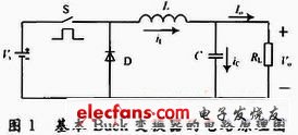
When the switch S is turned on, the freewheeling diode D is turned off due to the reverse voltage, and the current iL flowing through the inductor L linearly increases. On the load resistor RL, the current flows through Io, and the output voltage across the RL is Vo. The polarity is positive and negative, as shown in Figure 1. At iL "Io", capacitor C is in a charged state. When the switch S is turned off, the freewheeling diode D is turned on due to the forward voltage, iL linearly decreases. At iL "Io, the capacitor C is in a discharged state to maintain the output current Io and the output voltage Vo.
2 high power intrinsically safe LC-Buck converter
2.1 Composition of high-power intrinsically safe LC-Buck converter
It can be seen from the foregoing that the main factors affecting both the electrical index and the intrinsic safety performance index are the selection of the inductance and the capacitance and the selection of the switching frequency. Therefore, the design of the intrinsically safe switching converter is actually to select the appropriate switching frequency, inductance and output filter capacitor to ensure that the circuit parameters meet the requirements of the electrical specifications, so that when the fault occurs and the short circuit occurs, the generated The discharge energy is small enough to ignite the explosive gas.
Due to the above contradiction, this paper adds an LC filter circuit to the output of the basic Buck converter, so that the Buck converter can meet the electrical performance index and the intrinsic safety performance requirements at the same time when the inductance and capacitance are not large. Can increase the output power.
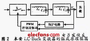
The block diagram of the composition of the intrinsically safe LC-Buck converter is shown in Figure 2.
2.2 Basic working principle of intrinsically safe LC-Buck converter
The intrinsically safe LC-Buck converter consists of a basic Buck converter and a second-order L, C low-pass filter. The main circuit structure is shown in Figure 3.
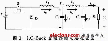
It can be seen from Fig. 3 that the LC-Buck converter is composed of a primary L and C filter circuit at the output of the basic Buck converter, and is mainly composed of the following parts: a switch tube S controlled by PWM; a freewheeling diode D; energy storage inductor L1; output filter inductor L2; output filter capacitor C1, C2 and load resistor RL. Where Vi is the input DC voltage; Vo1 is the first stage output voltage, and Vo is the second stage output voltage.
The operating principle of the LC-Buck converter is analyzed in one switching cycle. When the switch S is turned on, the freewheeling diode D is turned off due to the reverse voltage, and the current iL1 flowing through the inductor L1 linearly increases, and the energy storage inductor L1 converts the electric energy into magnetic energy and stores it in the inductor L1 when iL1 "Io" The capacitor C1 enters a charging state. When the switch S is disconnected, since the current flowing through the energy storage inductor L1 cannot be abruptly changed, a left negative right positive self-induced potential is induced at both ends of L1, so that the freewheeling diode D is turned on, and L1 turns the original The stored magnetic energy is converted into electrical energy to be supplied to the load. At this time, the inductor current iL1 linearly decreases, and when iL1 "Io, the capacitor C1 enters a discharge state. The LC-Buck converter consists of a second-order low-pass filter composed of an inductor L2 and a capacitor C2 throughout the dynamic operating range, and effectively attenuates the ripple voltage Vpp1 on the first-stage output voltage Vo1, so that the second-stage output voltage Vo The upper ripple voltage Vpp can meet the specified electrical performance requirements in the case of small inductance and small capacitance.
3 Experimental verification
In the case where the input voltage, switching frequency, equivalent capacitance, and equivalent inductance are the same, the maximum output power of the two converters is obtained. The specific indicators are as follows:
The input voltage is yi=21~27 V, the operating frequency is f=300 kHz, and the load resistance RL ranges from 10 to 100 Ω. The maximum equivalent capacitance is Ce, max = 5μF, the maximum equivalent inductance is Le, max = 20μF, and the maximum ripple voltage is Vpp, max = 1%Vo. L1 = 18 μH, C1 = 1 μF, L2 = 15 μH, and C2 = 0.6 μF.
The relationship between the output power and the load resistance of the basic intrinsically safe Buck converter and the intrinsically safe LC-Buck converter under a certain load variation range is shown in Fig. 4.
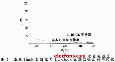
It can be seen from Fig. 4 that under the same input conditions and the same equivalent inductance and equivalent capacitance, the maximum output power of the intrinsically safe LC-Buck converter is larger than the maximum output power of the basic intrinsically safe Buck converter. many. It shows that the LC filter is used at the output of the basic intrinsically safe Buck converter, which can greatly improve the output power of the intrinsically safe Buck converter, and can effectively reduce the capacity of the energy storage component inductance and capacitance. It reflects the superiority of the LC-Buck converter.
4 Conclusion
In this paper, the composition and working principle of the basic Buck converter are analyzed firstly. Secondly, the intrinsically safe Buck converter with LC filtering is proposed to improve the output power of the converter. The composition and principle of the LC-Buck converter are analyzed. Finally, the experimental results show that the LC-Buck converter can greatly improve the output power of the intrinsically safe circuit.
Health Care heat film is mainly used for Far Infrared Sauna Room heat film,health care product, Body Heat Film ,eye massage thin heated element,Infrared Heating Jacket, Flexible Heating Flim for ski suit,Heating Flim For Diving Suit.
we are a professional and leader Chinese exporter of heat film,Customization options (for example: SMT components, flex cable and connectors) can provide the perfect complete solution that can significantly reduce assembly time and increase productivity.Providing a variety of complex shapes design, and different power designs. Membrane in the same piece electrically heated heating circuit can be designed and holding circuit,we are looking forward to your cooperation.
Health Care Heating Film,Carbon Heating Film,Infrared Heat Film,Infared Heating
ShenZhen XingHongChang Electric CO., LTD. , https://www.xhc-heater.com