Differential amplifier circuit basics
The composition of the circuit
As shown in (a), when the temperature changes, the collector potential changes, causing the output voltage to change. If the direct coupling method is used, this change will be amplified step by step, making the circuit unable to work properly.
Using the circuit shown in (b), the circuit with the same circuit parameters and the same tube characteristics is used. Then the static potential of the collectors of the two tubes will be equal when the temperature changes. The circuit uses the potential difference of the collectors of the two tubes as Output, it overcomes the temperature drift.>
Common mode signal: For the circuit shown in Figure (b), when the signals added by uI1 and uI2 are input signals of equal magnitude and polarity, they are called common mode signals.
Analysis of the common-mode input signal: when the circuit inputs the common-mode signal, due to the symmetry of the circuit parameters, the current generated by the T1 tube and the T2 tube
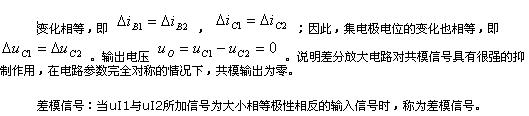
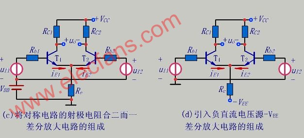
The emitter resistors Re1 and Re2 are combined into one and become a resistor Re. As shown in (c), the current change in Re is zero under the action of the differential mode signal, that is, Re has no feedback effect on the differential mode signal ( It is equivalent to a short circuit), which greatly improves the amplification ability of the differential mode signal.
In order to simplify the circuit and facilitate the adjustment of the Q point, and also to make the power supply and the signal source "common ground", a typical differential amplifier circuit as shown in (d) is generated.
3Pans Buffet Server,Electric Warming Tray Buffet Server,Buffet Server Warming Tray,3Pans Buffet Server Warmer
Shaoxing Haoda Electrical Appliance Co.,Ltd , https://www.zjhaoda.com