Design of portable ECG acquisition and control system
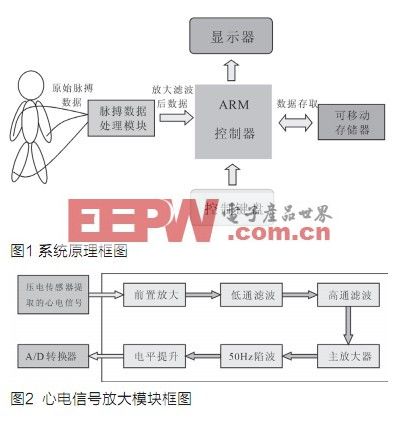
The system design consists of a microcontroller LPC2478 based on ARM7TDMI-S core on hardware, a re-writable low-power U disk, a dot matrix LCD display module, etc .; an ECG dynamic acquisition and storage instrument; the software uses embedded real-time operation As the system control platform, the system mC / OSâ…¡ improves the reliability of the system. The system can continuously record the subject's electrocardiogram changes from 24 to 48 hours. During the examination, the subject can carry it with him without affecting his daily life and work. It can make dynamic continuous monitoring records for a long time, a large-capacity U disk and USB2. The emergence of the 0 protocol makes data transmission more and more convenient and fast, which provides conditions for portable handheld mobile storage ECG devices. The schematic diagram of the system is shown in Figure 1.
System implementation
The main module block diagram of the system is shown in Figure 2. Since the ECG signal collected by the electrode belongs to the ultra-low frequency (0.5 ~ 100Hz) weak signal (0.1 ~ 5mV) under the background of strong noise, a pre-amplification part is required to amplify the weak ECG signal with high fidelity and pass low-pass filtering , High-pass filtering and 50 Hz notch filtering to remove interference, it can be sent to the LPC2478 A / D converter AIN0 for A / D conversion.
The pre-amplifier circuit is composed of input follower, instrument amplifier, and right leg floating drive. In order to increase the input impedance and obtain more ECG signals, the input follower uses a high-precision operational amplifier OPA427 to receive the heart from the left and right hands. The electric signal is sent to the instrument amplifier after being adjusted, and the signal after the first-stage inverting amplification by the high-precision instrument amplifier is sent to the low-pass filter. The common-mode noise in the original ECG signal is returned to the human body after first-stage amplification. They are superimposed on each other, which can reduce the absolute value of the common mode interference of the human body and improve the signal-to-noise ratio.
In the low-pass and high-pass filtering parts, since the ECG signal is a low-frequency signal, in order to remove high-frequency interference, low-pass filtering is also required. The cut-off frequency of the low-pass filter is 110Hz. The temperature drift of the amplifier, changes in skin resistance, breathing and human movement will cause the so-called "baseline drift" phenomenon of the ECG signal, that is, the output ECG signal will be on a certain horizontal line Move up and down slowly. From the frequency spectrum, these effects can be attributed to a low-frequency noise interference, so use a high-pass filter to filter out this part of the interference. In the main amplifier part, the total gain of the entire ECG amplifier circuit is set by adjusting the resistance RP1 of the potentiometer. The main amplifier uses a low power consumption and low noise operational amplifier TLC225. The 50Hz frequency notch part is mainly used to filter out the power frequency interference that enters the circuit in a differential mode signal. The level-up part is used to convert the bipolar signal into a unipolar signal so that it can be directly fed into AIN0.
hardware design
Hardware platform
Negative pressure generating circuit
Since the OPA4277, AD620 and TLC2254 chips need to use negative pressure in the data amplification and filtering circuits of the original ECG data processing, a negative pressure generating circuit is added to the circuit. The main application of the voltage conversion chip MC34063 generates a negative pressure of -12V through vibration. Then divide the voltage to get the -5V voltage required by the chip.
Signal preamplifier circuit
The composition and circuit diagram of the pre-amplifier circuit are shown in Figure 3. The pre-amplifier circuit is composed of three parts: input follower, instrument amplifier and right leg floating drive.
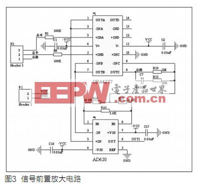
(1) Input follower: improve input impedance and obtain more ECG signals, using high-precision operational amplifier OPA4277, with ultra-low offset voltage l0 V, ultra-low offset offset ± 0.1V, maximum bias current l nA .
(2) Instrumentation amplifier: A high-precision instrumentation amplifier AD620 is used according to the system design requirements. The maximum input offset is 50mV, the input offset drift is 0.6mV / degrees Celsius, and the common mode rejection ratio is 120dB (G = 10). The gain range of this amplifier is 1 ~ 10000, and the relationship of its amplification gain is:
G = 1 + 49.4k / Rg
When G = 10, Rg is 5.489k, and the approximate value is 5.5k.
(3) Right leg floating drive: extract the common mode noise mixed in the original ECG signal, after one-stage inversion amplification, and then return to the human body, superimpose each other to reduce the absolute value of human body common mode interference To improve the signal-to-noise ratio, the main application of high-precision operational amplifier OPA4277.
High-pass and low-pass filter circuits
Since the ECG signal is a low-frequency signal, in order to remove high-frequency interference, low-pass filtering is also required. The low-pass filter uses a normalized fourth-order low-pass filter with a cut-off frequency of 100 Hz and sufficient steepness at the frequency corner to avoid interference from high-frequency signals. Considering the component error, the cut-off frequency is set to 110 Hz. The low-pass and high-pass filter circuits are shown in Figure 4. The amplifier uses a low-power, low-noise operational amplifier TLC2254. The power supply current of each channel is 35mA.

Main amplifier, 50Hz power frequency notch and level boost
The main amplifier circuit diagram sets the total gain of the entire ECG amplifier circuit by adjusting the resistance PI of the potentiometer. The main amplifier uses low power consumption and low noise operational amplifier TLC2254. Although the preamplifier circuit has a strong suppression effect on common mode interference, some of the interference enters the circuit in a differential mode signal, and the frequency is within the frequency band of the ECG signal, plus various other unstable factors, after After amplification, low-pass filtering, high-pass filtering and main amplifier, the output still has interference and must be specifically filtered out.
The ECG signal after passing through the trap is bipolar. The MD chip in the system can only quantify the unipolar signal. Therefore, the bipolar signal is converted into a unipolar signal by TLC2254.
LCD module
This system uses the MGLS12864 LCD module. Since this LCD does not have an internal character generator, any characters and Chinese characters displayed on the screen must be established in advance, and then displayed in a graphical manner. MGLS12864 module is connected with LPC2478, D0 ~ D7 are data / command bidirectional bus, CS is chip select signal, RES is reset signal, D / I is data / command select signal, R / W is read and write command signal, CE is control allowed signal.
software design
operating system
This system requires high real-time performance for data processing, data display and network transmission. A reliable RTOS is the guarantee for the stable and effective operation of the system, so we will transplant the mC / OS II real-time operating system on LPC2478 to meet the system Strict requirements for multithreading and hard real time.
mC / OS II is a mature and stable preemptive real-time kernel. Based on priority scheduling, it supports 56 user tasks and provides task communication mechanisms such as semaphores, mailboxes, and message queues, which can greatly improve CPU utilization efficiency. Since tasks are executed based on priority, if one of the tasks runs, the other high priority can be repaired by the monitoring program of the running system, so it is widely used in high-security occasions. And the mC / OS II source code is open and easy to transplant. There are a lot of successful cases in the 32-bit ARM-based microprocessor. In mC / OS II, each task is infinitely looped and is in one of five states: sleep state, ready state, running state, suspend state and interrupt state.
2. A / D conversion and transfer USB module:
The ECG signal amplified by the front-end ECG signal amplification module is directly sent to the P0.23 pin of the LPC2478 chip for A / D conversion. The converted data is an unsigned 32-bit data format, which is placed in the cache array Send to USB for storage, and leave it for LCD display output, the specific implementation process is:
First, you need to create two data cache areas "GcWritFileData [DATA_N]" and "GcReadFileData [DATA_N]" as "write file buffer" and "read file buffer", initialize the mC / OS II operating system, create for processing A / D conversion task Task0 and task Task1 for LCD display, start the multitasking environment, first initialize the hardware platform in Task0, set P0.23 to AIN0 [0] function, as the input lead for A / D conversion Pin, set the ADC module, set the conversion clock, etc., directly start the ADC conversion, the reference voltage for conversion is the 2.5V voltage provided by the precision constant voltage source, and finally the conversion result is saved to the "write file buffer". Then initialize the USB HOST and create the file system task "OSFileTask", create and open a file named "ECD.dat" with the "OSFileOpen" function, and write the data of the "GcWritFileData" write file buffer through the "OSFileWrite" function Go to the U disk, and judge whether the file writing is successful by its return value. After writing the file, use the "OSFileRead" function to read and write the data of the "GcWritFileData" write file buffer to the "GcReadFileData" read file buffer, and then write 1. Compare the data in the read file buffer to determine whether the data written to the file is correct. At this point, the process of receiving data from A / D conversion and transferring to USB is completed. The program flow chart is shown in Figure 5.
Gaming Headset With Microphone/Good Gaming Headset with mic for pc/Gaming Headset Pc
Features:
1. Popular gaming headset with custom logo color
2. Manufacture with competitive price & good quality
3. Imprint customer's logo as requested4. Excellent sound performance
5. Custom packing design service
6. Samples are available
7. Headphone for personal use, for gift to friends

Gaming Headset With Microphone
Gaming Headset With Microphone,Gaming Headset Pc,Ps4 Headset,Childrens Headphones With Microphone
Shenzhen Greater Industry Co., Ltd. , https://www.szgreater.net