Based on Zigbee communication protocol, a peripheral circuit of intelligent air conditioning control system is designed. The system adopts CC2530 module as the core configuration, adopts DS18B20 temperature sensor, Nokia5110 liquid crystal and computer monitoring system and other components. It is connected with the host computer, single chip microcomputer and sensor to collect, store and control the measurement data of the system, thus realizing the remote control of the air conditioning system. control. In-depth study of the anti-jamming capability of the internal antenna enhancement system of the PCB.
The designed wireless intelligent air conditioning system can effectively monitor and control the indoor temperature in real time.
In today's society, people's requirements for quality of life are getting higher and higher, and traditional home appliances can no longer meet people's needs, so the concept of smart homes quietly rises. Smart home appliances are consumer electronic products that integrate microcomputers and communication technologies into traditional home appliances, make them intelligent and have network terminal functions, and can acquire and process information anytime and anywhere. The important feature is to transmit digital information through the Internet. . Based on this, a peripheral circuit of intelligent air conditioning control system based on ZigBee communication protocol is designed. Combined with the original air conditioning control system, it can remotely monitor and control the operation of the air conditioner in real time.
1 Advantages of ZigBee Technology Since the 21st century, the most popular wireless LAN communication has WIFI, Bluetooth, and ZigBee, but Bluetooth has a short transmission distance, WIFI has high cost and high power consumption, and ZigBee has low cost and low power consumption. The low complexity advantage is suitable for wireless control systems with short distance and low transmission information, and is more in line with the green concept of wireless smart home appliances with high quality and low price, energy saving and emission reduction. Therefore, the smart home appliance control system based on ZigBee communication protocol will be the future development direction.
2 ZigBee protocol stack structure The ZigBee protocol stack structure consists of a set of modules called layers. The next layer performs a specific service for the above layer, that is, the data entity provides the data transfer service, and the management entity provides all other services. The upper layer is provided by the service entity through the service access point to provide an interface. The physical layer and media medium access layer are defined by the IEEE 802.15.4 protocol standard, and the network layer and application layer are developed by the ZigBee Alliance. The physical layer provides the data connection of the original bit stream for the upper layer, the MAC layer controls the physical addressing of the data packet, the network layer determines the network transmission path, and the application layer serves the application. Each layer of the organization communicates between adjacent layers through a data service interface and a management service interface.
3 PCB internal antenna design When using the PCB internal antenna, in order to enhance the system's anti-interference ability, it is necessary to design a precise antenna length. It can be known from the CC2530 chip that the frequency f of the system is 2.4 GHz, and the propagation speed of the light C0 is 3×10⁸ m/s, and the wavelength in the vacuum can be calculated, as shown in the formula (1):
λ=C0/f (1)
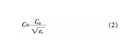
When electromagnetic waves propagate in other media, the propagation velocity in the medium can be calculated from the dielectric constant of the medium and vacuum, as shown in equation (2):
4 System design of the overall circuit A complete ZigBee intelligent air conditioning system requires a coordinator, one or more routers and a number of terminal nodes, in order to complete the network construction, path allocation and data acquisition and transmission tasks. Based on the ZigBee protocol design of the peripheral circuit, the system block diagram is shown in Figure 1. The structure of the peripheral circuit of the wireless intelligent air conditioning system is a star-shaped network structure, which is measured by a full-function coordinator (acquisition module), an LCD liquid crystal and a temperature sensor. The node is composed of a terminal node (sensing module).
5 System hardware design The hardware circuit is mainly composed of a sensing module, an acquisition module and a power module.
5.1 Selection of Communication Module In order to increase the data storage and processing capability of the central node during the design process, the CC2530 with 256 K Flash and standard 8051 enhanced processor was selected as the core module.
The CC2530 module is a 2.4 GHz wireless RF microcontroller that is fully compatible with the 8051 core and supports the IEEE802.15.4 protocol. This module can meet the Z-Stack operating memory capacity requirements. It supports 2.0 to 3.6 V supply voltage and has three power management modes. Mode: wake mode, sleep mode, terminal mode; transmission distance greater than 75 m, maximum transmission rate 250 kbps, very suitable for application on smart air conditioners. The schematic diagram of the minimum system based on the CC2530 module is shown in Figure 2.
5.3 Hardware Design of Sensing Module The sensing module is the terminal node of the intelligent air conditioning control system. In addition to the components of the acquisition module, the sensing module also has a temperature sensor DS18B20 and an LCD liquid crystal display portion. The sensing module requires a serial cable to enable two-way communication between the DS 18B20 temperature sensor and the PC.
When the temperature sensor detects the temperature, the CC2530 processes the data, prepares it for transmission, displays it on the LCD, and sends it to the acquisition module. After the upper computer sets the temperature, it is transmitted to the sensing module through the acquisition module and displayed on the LCD. When transmitted or received, the sensing module enters sleep mode, allowing the controller to enter a low power mode to extend battery life.
5.4 Power Circuit Design The power circuit supplies power to other functional modules of the intelligent air conditioning system to ensure the normal operation of the module. In the module, the download device and the debug device need 5 V power supply, and the chip CC2530 needs 3.3 V power supply, so the voltage conversion chip is used for level conversion. In order to fully meet different working environments, the system uses three power supply modes: battery power supply, USB power supply, and regulated power supply DC power supply.
6 System software design system integrated development environment using IAR Embedded Workbench ForC8051, in this environment to complete the programming, compiling, debugging of CC2530 program, use CC Debugger and SmartRF Flash Programmer to complete the download of the program. The software design mainly adopts the free ZigBee protocol software supported by TI's CC2530, and uses C language as the programming language to control the wireless intelligent air conditioner by modifying the APP program based on the Z-Stack universal template.
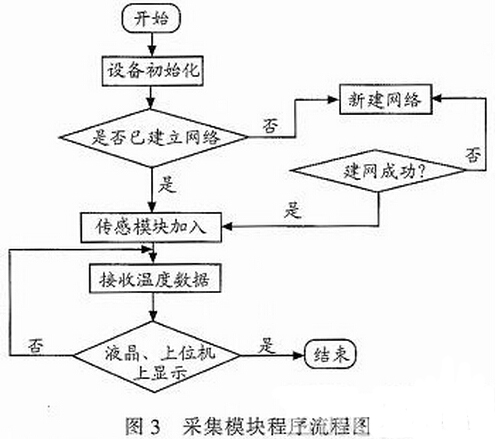
6.1 Acquisition Module Software Design The acquisition module program includes system initialization, channel scanning, coordinator establishment of the network, allowing the child node to access the network and receiving node data and other code programs. After the system is powered on, first initialize the software and hardware, establish a network and assign an ID address to each node joining the network, and then the system enters the listening state. When the coordinator receives the command sent by the wireless sensor module terminal, it sends a control command. At the node, the temperature control of the air conditioner can be realized. The flow chart of the acquisition module program is shown in Figure 3.
When the interval between device addresses is 0, there is no router in the networking, so no sensing device can be accepted. The sensing module can be assigned an address when the interval between addresses is greater than zero.
When the acquisition module assigns addresses to multiple sensing modules, the first sub-module is first assigned a networking address that is one greater than its own address, and then incremented by the interval Cskip(d) between the addresses, followed by Assigned to other submodules. The address assignment is as shown in equation (7):
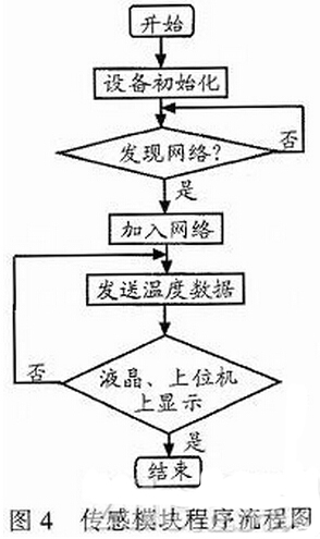
6.2 Sensing Module Software Design The sensing module will automatically join the network, issue a binding request, and wait for the acquisition module to bind the response. If there is no response, the sensor module will continue to search continuously. If the binding is successful, the temperature data will be sent every 1 s, and then transmitted separately in two paths. One is transmitted to the acquisition module through wireless ZigBee technology, and the other is directly displayed on the LCD liquid crystal. When the sensing module receives the command data sent by the acquisition module through the wireless ZigBee technology, the data is also displayed on the LCD screen. The sensor module program flow chart is shown in Figure 4.
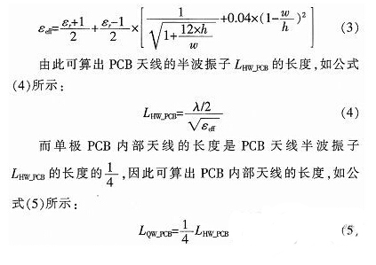
8 Conclusion The system is based on the design of ZigBee-based wireless intelligent air conditioner peripheral circuits. The wireless intelligent air conditioning control system consisting of CC2530, DS18B20 and Nokia5110 LCD screens has the advantages of strong portability, power saving, flexibility and compactness, and can be applied to many occasions to facilitate people's lives. The length of the PCB internal antenna is designed to be 36.33 mm to enhance the anti-interference ability and accurately transmit and receive data. The system transmits data wirelessly, avoiding the shortcomings of the traditional cable, and is more suitable for the needs of today's society.
The designed wireless intelligent air conditioning system can effectively monitor and control the indoor temperature in real time.
In today's society, people's requirements for quality of life are getting higher and higher, and traditional home appliances can no longer meet people's needs, so the concept of smart homes quietly rises. Smart home appliances are consumer electronic products that integrate microcomputers and communication technologies into traditional home appliances, make them intelligent and have network terminal functions, and can acquire and process information anytime and anywhere. The important feature is to transmit digital information through the Internet. . Based on this, a peripheral circuit of intelligent air conditioning control system based on ZigBee communication protocol is designed. Combined with the original air conditioning control system, it can remotely monitor and control the operation of the air conditioner in real time.
1 Advantages of ZigBee Technology Since the 21st century, the most popular wireless LAN communication has WIFI, Bluetooth, and ZigBee, but Bluetooth has a short transmission distance, WIFI has high cost and high power consumption, and ZigBee has low cost and low power consumption. The low complexity advantage is suitable for wireless control systems with short distance and low transmission information, and is more in line with the green concept of wireless smart home appliances with high quality and low price, energy saving and emission reduction. Therefore, the smart home appliance control system based on ZigBee communication protocol will be the future development direction.
2 ZigBee protocol stack structure The ZigBee protocol stack structure consists of a set of modules called layers. The next layer performs a specific service for the above layer, that is, the data entity provides the data transfer service, and the management entity provides all other services. The upper layer is provided by the service entity through the service access point to provide an interface. The physical layer and media medium access layer are defined by the IEEE 802.15.4 protocol standard, and the network layer and application layer are developed by the ZigBee Alliance. The physical layer provides the data connection of the original bit stream for the upper layer, the MAC layer controls the physical addressing of the data packet, the network layer determines the network transmission path, and the application layer serves the application. Each layer of the organization communicates between adjacent layers through a data service interface and a management service interface.
3 PCB internal antenna design When using the PCB internal antenna, in order to enhance the system's anti-interference ability, it is necessary to design a precise antenna length. It can be known from the CC2530 chip that the frequency f of the system is 2.4 GHz, and the propagation speed of the light C0 is 3×10⁸ m/s, and the wavelength in the vacuum can be calculated, as shown in the formula (1):
λ=C0/f (1)
When electromagnetic waves propagate in other media, the propagation velocity in the medium can be calculated from the dielectric constant of the medium and vacuum, as shown in equation (2):
4 System design of the overall circuit A complete ZigBee intelligent air conditioning system requires a coordinator, one or more routers and a number of terminal nodes, in order to complete the network construction, path allocation and data acquisition and transmission tasks. Based on the ZigBee protocol design of the peripheral circuit, the system block diagram is shown in Figure 1. The structure of the peripheral circuit of the wireless intelligent air conditioning system is a star-shaped network structure, which is measured by a full-function coordinator (acquisition module), an LCD liquid crystal and a temperature sensor. The node is composed of a terminal node (sensing module).

5 System hardware design The hardware circuit is mainly composed of a sensing module, an acquisition module and a power module.
5.1 Selection of Communication Module In order to increase the data storage and processing capability of the central node during the design process, the CC2530 with 256 K Flash and standard 8051 enhanced processor was selected as the core module.
The CC2530 module is a 2.4 GHz wireless RF microcontroller that is fully compatible with the 8051 core and supports the IEEE802.15.4 protocol. This module can meet the Z-Stack operating memory capacity requirements. It supports 2.0 to 3.6 V supply voltage and has three power management modes. Mode: wake mode, sleep mode, terminal mode; transmission distance greater than 75 m, maximum transmission rate 250 kbps, very suitable for application on smart air conditioners. The schematic diagram of the minimum system based on the CC2530 module is shown in Figure 2.

5.3 Hardware Design of Sensing Module The sensing module is the terminal node of the intelligent air conditioning control system. In addition to the components of the acquisition module, the sensing module also has a temperature sensor DS18B20 and an LCD liquid crystal display portion. The sensing module requires a serial cable to enable two-way communication between the DS 18B20 temperature sensor and the PC.
When the temperature sensor detects the temperature, the CC2530 processes the data, prepares it for transmission, displays it on the LCD, and sends it to the acquisition module. After the upper computer sets the temperature, it is transmitted to the sensing module through the acquisition module and displayed on the LCD. When transmitted or received, the sensing module enters sleep mode, allowing the controller to enter a low power mode to extend battery life.
5.4 Power Circuit Design The power circuit supplies power to other functional modules of the intelligent air conditioning system to ensure the normal operation of the module. In the module, the download device and the debug device need 5 V power supply, and the chip CC2530 needs 3.3 V power supply, so the voltage conversion chip is used for level conversion. In order to fully meet different working environments, the system uses three power supply modes: battery power supply, USB power supply, and regulated power supply DC power supply.
6 System software design system integrated development environment using IAR Embedded Workbench ForC8051, in this environment to complete the programming, compiling, debugging of CC2530 program, use CC Debugger and SmartRF Flash Programmer to complete the download of the program. The software design mainly adopts the free ZigBee protocol software supported by TI's CC2530, and uses C language as the programming language to control the wireless intelligent air conditioner by modifying the APP program based on the Z-Stack universal template.
6.1 Acquisition Module Software Design The acquisition module program includes system initialization, channel scanning, coordinator establishment of the network, allowing the child node to access the network and receiving node data and other code programs. After the system is powered on, first initialize the software and hardware, establish a network and assign an ID address to each node joining the network, and then the system enters the listening state. When the coordinator receives the command sent by the wireless sensor module terminal, it sends a control command. At the node, the temperature control of the air conditioner can be realized. The flow chart of the acquisition module program is shown in Figure 3.

When the interval between device addresses is 0, there is no router in the networking, so no sensing device can be accepted. The sensing module can be assigned an address when the interval between addresses is greater than zero.
When the acquisition module assigns addresses to multiple sensing modules, the first sub-module is first assigned a networking address that is one greater than its own address, and then incremented by the interval Cskip(d) between the addresses, followed by Assigned to other submodules. The address assignment is as shown in equation (7):

6.2 Sensing Module Software Design The sensing module will automatically join the network, issue a binding request, and wait for the acquisition module to bind the response. If there is no response, the sensor module will continue to search continuously. If the binding is successful, the temperature data will be sent every 1 s, and then transmitted separately in two paths. One is transmitted to the acquisition module through wireless ZigBee technology, and the other is directly displayed on the LCD liquid crystal. When the sensing module receives the command data sent by the acquisition module through the wireless ZigBee technology, the data is also displayed on the LCD screen. The sensor module program flow chart is shown in Figure 4.

8 Conclusion The system is based on the design of ZigBee-based wireless intelligent air conditioner peripheral circuits. The wireless intelligent air conditioning control system consisting of CC2530, DS18B20 and Nokia5110 LCD screens has the advantages of strong portability, power saving, flexibility and compactness, and can be applied to many occasions to facilitate people's lives. The length of the PCB internal antenna is designed to be 36.33 mm to enhance the anti-interference ability and accurately transmit and receive data. The system transmits data wirelessly, avoiding the shortcomings of the traditional cable, and is more suitable for the needs of today's society.
0 times
Window._bd_share_config = { "common": { "bdSnsKey": {}, "bdText": "", "bdMini": "2", "bdMiniList": false, "bdPic": "", "bdStyle": " 0", "bdSize": "24" }, "share": {}, "image": { "viewList": ["qzone", "tsina", "tqq", "renren", "weixin"], "viewText": "Share to:", "viewSize": "16" }, "selectShare": { "bdContainerClass": null, "bdSelectMiniList": ["qzone", "tsina", "tqq", "renren" , "weixin"] } }; with (document) 0[(getElementsByTagName('head')[0] || body).appendChild(createElement('script')).src = 'http://bdimg.share. Baidu.com/static/api/js/share.js?v=89860593.js?cdnversion=' + ~(-new Date() / 36e5)];
We are saleing Membrane Switch For Schneider,provides the product information.
Membrane Switch for Schneider are widely used for medical and industrial equipment, research shows, machinery equipment, industrial control, man-machine interface, industrial automation integrated workstation, POS, CNC etc. we have a lot of membrane switch for Schneider, standing some of our inventory stock.
Membrane Switch for Schneider
Membrane Switch For Schneider,Membrane Keyboard For Schneider,Membrane Keypad For Schneider
GUANGZHOU VICPAS TOUCH TECHNOLOGY CO.,LTD , https://www.touchsuppliers.com