The tension of the fabric is an indication of the tightness of the contact between the fabric and the sanding roller. In the process of sanding, the greater the tension of the cloth surface, the tighter the contact between the cloth surface and the sanding roller, and the better the sanding effect. However, the tension should not be too large, otherwise the fabric strength will decrease more, affecting the performance of the fabric, making the sanding effect worse, and the fabric surface and the pile hair are uneven, resulting in the products such as the willow. Maintaining a constant tension on the fabric avoids cracks such as cracks in the surface fluff, so it is critical to maintain the actual tension of the fabric constant on a high speed running sander.
2 Main working unit of the sanding machine The feeding roller, the leading roller, the rear roller, the upper roller and the discharging roller are the guiding system rollers, which are controlled by the servo system. The cylinder, the left and right grinding rollers and the adjustable speed expansion roller are controlled by frequency conversion. The non-speed adjustable expansion roller follows the adjustable speed expansion roller to start and stop.
The tension control process is to establish a constant tension closed-loop control subsystem with the fabric tension as the control amount and the guide roller rotation speed as the control amount. The PCC receives the value detected by the tension sensor in real time through the analog input port to determine the tension level. According to the tension setting value, the PCC internal PID control algorithm is used to calculate the servo motor speed change amount, and the pulse is sent through the high-speed pulse output port. The signal is applied to the servo drive to drive the motor to rotate, ensuring constant system tension during operation.
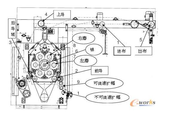
Figure 2.1 The main working unit of the sanding machine
(1) Feeding roller (2) Leading roller (3) Rear roller (4) Upper roller (5) Cloth roller (6) Cylinder (7) Left grinding roller (8) Right grinding roller (9) Speed ​​regulation expansion roller (10) Non-speed adjustable expansion roller 3 Electronic control system block diagram The electronic control system of this project is mainly composed of five parts: touch screen, PCC controller, tension sensor, servo control system and frequency conversion control system. The system control block diagram is shown in Figure 3.1.

Figure 3.1 Overall block diagram of the sanding electrical control system
The core of the design of the electronic control system in this project is to ensure the constant tension of the fabric during normal operation. Through the tension sensor detection and the closed loop control of the fabric feed speed, the communication method is used to synchronize the real-time control of constant tension and multi-motor. Synchronous coordinated movement between. That is to say, the multi-axis transmission tension control system is adopted to design a tension sampling method that can reflect the real change. During the running process, the real-time tension of the fabric is detected by four tension sensors, and then compared with the set tension value, the PCC internal PID module The actual tension is automatically adjusted to ensure that the fabric has a constant tension during operation. The touch screen uses the B&R Power Panel 300 embedded, and the servo motor uses a B&R 8MS synchronous servo motor.
4 PCC-based software framework design system software adopts modular programming. The software part mainly consists of modules such as “PT interface designâ€, “master-slave communicationâ€, “inverter controlâ€, “servo motor control†and “tension adjustmentâ€. Here we mainly introduce the design of the tension adjustment module.
4.1 The PCC controlled software framework switch and four servo control programs and drivers are written in the PCC. The PCC software framework is shown in Figure 4.1.
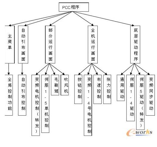
Figure 4.1 Software Framework of PCC
4.2 PCC software framework The control program of the upper servo 5 and 4 inverters is written in the PCC. The PCC software framework is shown in Figure 4.2.
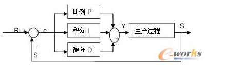
Figure 4.2 PCC software framework diagram
4.3 Tension adjustment module design Since the servo control system can not only control the speed but also control the position, the servo control is more accurate and reliable than the frequency conversion speed regulation. Therefore, the tension adjustment control in this design uses a servo control system, and its control software uses PCC's built-in PID adjustment.
The PID regulator consists of a proportional regulator (P), an integral regulator (I) and a differential regulator (D). Figure 4.3 shows the block diagram of the PID control system.

Figure 4.3 PID control system block diagram
In the figure, R is the set desired value, Y is the control variable, S is the actual output value, and e is the control deviation value (e=RS).
Working principle: directly adopt the PID instruction programming module provided in PCC, obtain the specified tension signal from the analog input channel--->AD--->tension digital quantity---> enter the PID module, according to the setting parameters (proportion The coefficient, the derivative time, the integration time, etc.) are calculated by the PID---->the adjusted tension value, and the operation result is placed on the output channel. The adjusted frequency value is calculated by formula conversion.
4.3.2 PID control algorithm PID control is controlled according to the deviation e(t) between the given value R(t) and the actual output value S(t). The proportional (P), integral (I), and differential (D) deviations are linearly combined to form a control amount to control the controlled object.
The basic operation of the PID control algorithm is as follows:
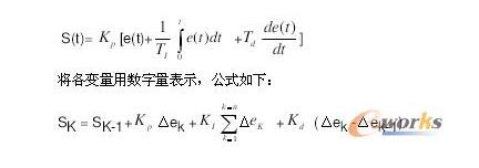
In the tension control, considering the calculation speed of the PCC and the requirements of the servo control system speed and control accuracy, the sampling period is set to 200 ms.
In the formula, SK is the output pulse frequency of the Kth servo motor, and the speed of the servo motor is controlled. SK-1 is the last pulse output frequency value.
Δek is the difference between the number of pulses actually output and the number of pulses that should be output.
Δek= ek- ek-1 is the number of deviations obtained for the Kth sampling.
Δek-1= ek-1- ek-2 is the number of deviations obtained for the K-1th sampling.
Kp, Ki, and Kd are the proportional coefficient, the integral coefficient, and the differential coefficient, respectively.
The actual debugging process can debug Kp, Ki, Kd, ​​select reasonable values, and ensure that the deviation control is within a reasonable range.
4.3.3 Tension Control Program Flow Chart The tension control program flow chart is shown in Figure 4.4.
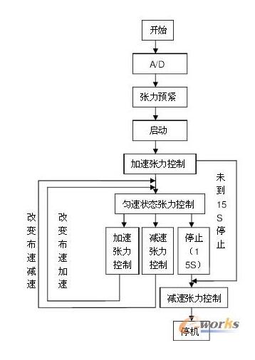
Figure 4.4 Tension Control Program Flow Chart
First, the value of the tension sensor is transmitted to the analog input channel of the PCC, and is converted into a digital quantity by analog quantity. Then, the tension pre-tightening can be performed first, so that the tension before the operation reaches about 70% of the set value, so as to avoid the tension after the whole machine is started. Loosen immediately.
After the whole machine is started, the servo and variable frequency control system starts to accelerate from 0, and the tension is controlled in real time during the acceleration process. After the acceleration for 15s, the system enters the constant speed operation stage. At this time, the acceleration tension control is closed, and the uniform speed tension control is started to realize the real-time control of the tension in the uniform speed state. When the set value is changed at a constant speed, the acceleration or deceleration state is entered, and the time is 5 s. Tension control uses traditional PID control. When the whole machine stops, turn on the deceleration tension control until the machine stops.
5 Conclusion This design mainly discusses the mechanical control system of sanding finishing from the aspects of control system working principle, hardware structure and software module design. PCC is used as the core control unit, and the guide system is replaced with the servo control system to replace the inverter control system, so that the tension values ​​are more stable during the operation of the sander. Achieved technological breakthroughs, greatly improving production efficiency and system stability. After the fabric is processed by the sanding machine, the hand feels soft and smooth, the fluff is short and even, and some fabrics can achieve the effect of the hairless touch, which greatly improves the added value of the fabric.
CR Battery,CR Battery Types,Coin Cell Battery,CR Lithium Battery
Shenzhen Sunwind Energy Tech Co.,Ltd , https://www.sunwindbatterylm.com