1 Introduction
Beam controllable antennas are widely used in satellite, mobile TV, radar systems and other fields. The literature has carried out research on the radiation pattern control of the antenna. In the literature, a rectangular loop antenna is proposed. This antenna contains four feed points, and four beams pointing in different directions are obtained by changing the position of the feed point. A star antenna can form a beam offset pattern and a circular pattern. In the literature, an annular slot antenna is introduced, which shorts the antenna to the ground to achieve beam offset. The reconfigurable antenna reconstructs the antenna's resonant frequency, radiation pattern, polarization, etc. by changing its structure. The concept of a reconfigurable antenna solves the real problems of system cost and weight. In [4], a pattern reconfigurable antenna is proposed, which is controlled by switches to direct the beam in four different directions. Pin Diode Switches are often used to change the physical structure or size of an antenna.
In recent years, electromagnetic bandgap (EBG) structures have found wide applications in the field of antennas. The EBG structure is used to reduce mutual coupling between antenna elements. The EBG structure is used in antenna design to achieve wider bandwidth and higher efficiency. The same EBG structure can be used to control the radiation pattern of the antenna.
This paper proposes a new U-shaped slot microstrip antenna based on EBG structure. The EBG structure replaces part of the metal ground plane, and the current on the antenna patch is effectively controlled due to the introduction of the EBG structure. Through testing, the antenna's operating frequency is 5.5 GHz, and the maximum gain of radiation appears at 27.5 dBi at 22°. Through parameter analysis, it is found that the offset angle of the antenna beam is related to the EBG structure. According to this feature, the antenna pattern can be reconstructed, the design scheme is proposed, and its feasibility is verified by simulation.
2 antenna unit design and results
A schematic diagram of a novel U-shaped slot microstrip antenna is shown in FIG. Part of the metal ground plane of the microstrip antenna is replaced by an EBG structure. The dimensions of the U-shaped slot microstrip antenna are shown in Figure 2. The dielectric substrate was Arlon AD 270, and the relative dielectric constant εr1 = 2.7, and the dielectric thickness h = 3.5 mm. As shown in Figure 3, the EBG structure is presented in [11]. The detailed dimensions of the EBG structure are as follows: W = 0.12 λ0, g = 0.02 λ0, h = 0.04 λ0, r = 0.005 λ0, εr2 = 2.2, λ0 = 50 mm.
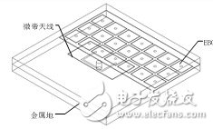
(a) 3D view
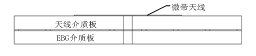
(b) side view
Figure 1 Schematic diagram of U-shaped slot microstrip antenna structure
The U-shaped slot microstrip antenna has the advantage of having a large number of adjustment variables, which can be optimized to achieve impedance matching. Figure 4 shows the simulation and test results of the antenna reflection coefficient. Compared with the simulation, the test result has a narrower bandwidth, with a center frequency of 5.5 GHz and a bandwidth of 4.99 GHz to 5.63 GHz. Figure 5 shows the radiation pattern of the microstrip antenna unit simulated and tested at a frequency of 5.5 GHz. The maximum radiation direction is 20° and the gain is 7.6 dBi. The angular offset direction is 22° and the gain is 7.75 dBi. The reason for the beam generation offset is that the EBG structure changes the current distribution on the microstrip antenna patch.
The offset angle of the antenna beam can be controlled by the number of rows of the EBG structure. Based on the above research results, increasing or decreasing the number of EBG rows can change the maximum radiation direction of the antenna. The simulation and test radiation patterns for different EBG structures are shown in Figures 6 and 7. Table 1 lists the EBG distribution and angle, gain test data, where the values ​​in parentheses are simulation results.
Figure 2 U-shaped patch patch top view
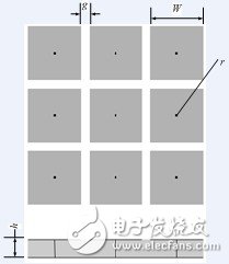
Figure 3 Schematic diagram of EBG structure
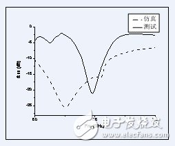
Figure 4 S11 simulation and test comparison
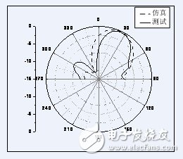
Figure 5 Antenna unit radiation pattern
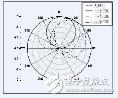
Figure 6 Simulated radiation pattern of different EBG distributions
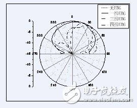
Figure 7 Radiation pattern of different EBG distribution test
Table 1 EBG distribution and gain angle table
EBG row number Angle (°) Gain (dBi)
One row 16(10) 7.95(8)
Three rows 22 (20) 7.75 (7.6)
Four rows 31 (36) 7.85 (7.34)
3 pattern reconfigurable antenna research
The turning on and off of the EBG patch and the nearby metal ground can change the radiation pattern, that is, design a pattern reconfigurable microstrip antenna unit. In this paper, two sets of PIN diode switches are used to control the on and off between the EBG patch and the metal ground. The positions of the switch 1 and the switch 2 are as shown in Fig. 8. In order to accurately simulate the actual switch, the PIN diode in the on state is equivalent to a 3Ω resistor in the simulation, and the diode in the off state can be equivalent to a capacitor of 0.025pF. Four different radiation patterns can be obtained by turning the two sets of switches on and off, as shown in Figure 9. When both sets of switches are turned on, it is equivalent to the EBG on both sides of the antenna is metal ground, the pattern does not shift; when the switch is off, it is equivalent to 4 rows of EBG working at the same time, the maximum gain appears at 31 °. When the switch 1 is turned on, the offset angle of the beam is 23° when the switch 2 is turned off; on the contrary, when the switch 2 is turned on and the switch 1 is turned off, only the three rows of EBGs are offset at an angle of 36° during operation. .
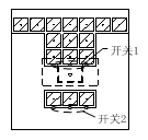
Figure 8 PIN diode position diagram
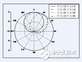
Figure 9 Antenna radiation pattern in four cases where the switch is switched on and off
4 Conclusion
In this paper, a novel U-shaped slot microstrip antenna is proposed. The use of an EBG structure instead of a partially microstrip antenna allows for maximum radiation direction control. The PIN diode is used as a switch to control the on and off between the EBG patch and the metal ground to achieve the purpose of controlling the beam pointing of the antenna, thereby realizing the pattern reconfigurable antenna unit.
Waveguide Coupler,Rf Directional Coupler,Coaxial Directional Coupler,Waveguide Directional Coupler
Chengdu Zysen Technology Co., Ltd. , https://www.zysenmw.com