0 Preface
The stepping motor is an open-loop control motor that converts the electric pulse signal into an angular displacement or a linear displacement. The total number of input pulses controls the total rotation angle of the stepping motor. The speed of the motor is determined by the number of input pulses per second, so the mechanical position is easy to realize. Precise control. Moreover, due to the low price and strong controllability of the stepping motor, it has been widely used in the field of automatic control of CNC machine tool transmission control. However, with the development of technology and the requirements of enterprise production, the traditional control system of stepping motor with microprocessor such as single chip microcomputer has exposed the following shortcomings: the single control strategy is not conducive to human-computer interaction, and the control circuit is complex. Low control precision, high production cost, insufficient system stability, low step resolution, lack of flexibility, high oscillation and noise at low frequencies, and limited by the mechanical structure and space of the stepper motor, step angle of the stepper motor It is impossible to be infinitely small, and it is difficult to meet the demand for high-precision open-loop control. Due to the simple programming method of FPGA, short development cycle and high reliability, it is more and more widely used in industrial control field. Based on the summary of FPGA's frequency division technology and stepping motor subdivision control principle, the PWM control technology is used to improve the resolution of stepper motor. Simulation and experiments show that the measures taken in this paper effectively implement stepper motor control. Efficient and precise control.
1 Stepper motor subdivision control principle
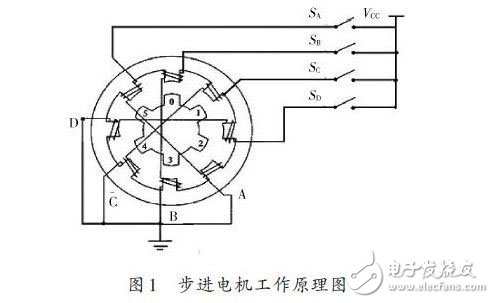
The working principle of the stepping motor is shown in Figure 1. For a four-phase stepping motor, the rotation of each phase winding can be controlled in a certain order to control the rotation of the motor. For example, when the switch B is turned on and the other switches are turned off, the B-phase magnetic poles are aligned with the rotors 0 and 3 under the action of the magnetic lines of force; when the switch C is turned on with the power source and the other switches are turned off, the action of the magnetic lines of force Next, the rotor rotates, and the magnetic poles of the No. 1 and No. 4 teeth and the C-phase winding are aligned. In the same way, the four-phase windings of A, B, C, and D are sequentially supplied with power, and the motor rotates in the A, B, C, and D directions.
In order to understand the shortcomings of stepper motors, it is also necessary to understand the step angle of the stepper motor. The step angle is defined as:
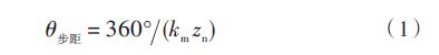
Where: km is the working beat coefficient of the stepper motor; zn is the number of teeth.
Due to the number of beats of the stepping motor and the number of teeth of the rotor, the step angle of the stepping motor cannot be very small, that is, the amount of rotation of each single step control is relatively large. In many precision control fields, the function of the stepping motor is up to Not required to use. Therefore, in order to improve the resolution of the stepper motor, it is necessary to use the subdivision control technology to optimize its control. Subdivision control is similar to interpolation. The basic principle is to subdivide the current in the motor winding and add a lot of intermediate current between the two control currents, so that the stepper motor can work in many intermediate states, thus making the stepping Each step of the motor is subdivided, the step angle is smaller, the resolution of the system is improved, and the performance is optimized. Subdivision control usually has two subdivision methods, one is to make the current subdivide according to the linear law change, and the other is to subdivide according to the equal step angle. In order to compare the advantages and disadvantages of the two subdivision methods, it is also necessary to understand the static range characteristics of the stepper motor.
![]()
Where: M is the electromagnetic torque; Mk is the maximum static torque when a certain winding current is used; for the reactive stepping motor, when the magnetic circuit saturation is not considered, Mk can be considered to be proportional to the square of the current i, and the negative sign indicates There is a 楞 relationship between the electromagnetic torque and the stator magnetic field, that is, the electromagnetic torque always blocks the position where the rotor leaves the minimum magnetic resistance of the magnetic field.
The three-phase reactive stepping motor is now used to analyze the two subdivision methods.
When the three-phase windings of the three-phase reactive stepping motor are respectively energized, the moment angle characteristics are sinusoidal curves of 120° electrical angles from each other, as shown in Fig. 2.
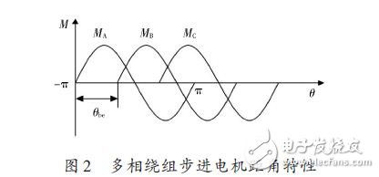
When the two phases A and B are energized, the currents are iA and iB respectively, and the corresponding static torques are MA and MB. The influence of the magnetic circuit is ignored, and the combined rectangular angle characteristics are superimposed on the two, as in the equation (3). ) shown:
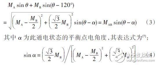
It can be seen from equations (3) and (4) that when the current of the stepping motor changes according to the linear law, the distance characteristics are as shown in Fig. 3(a). Since the amplitude of the angular feature is unequal due to the difference in energization current, the step angle of each subdivision step cannot be consistent. The ideal subdivided current waveform should have the same magnitude and shape of the step angle characteristics in each energized state, as shown in Figure 3(b).
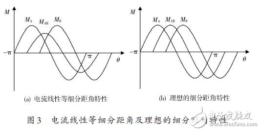
Therefore, the subdivision of the current according to the linear law makes the control precision of each substep after subdivision not equal. If subdivided by equal step angle, the step angle after subdivision is:

If the respective energization states are controlled strictly in accordance with the current distribution coefficient in the control circuit, it is possible to ensure that the control precision of each small step after subdivision is equal. Therefore, this paper uses the subdivision method of equal step angle.
2 Stepper motor subdivision control hardware implementation
In order to realize the stepping angle subdivision of stepping motor, this paper uses pulse width modulation (PWM) to achieve. PWM is to control the on/off of the switching device of the inverter circuit, so that the output end obtains a series of pulses of equal amplitude. These pulses are combined to form an equivalent waveform such as an equivalent sine wave or square wave. The quality of the equivalent output waveform is related to the step size of the pulse. That is, the more PWM channels are output at the same time, the higher the pulse density, the better the quality of the output equivalent waveform. The traditional stepping motor control system mostly uses the single-chip microcomputer as the microprocessor, and the single-chip microcomputer is a single-threaded microprocessor. Only one command can be executed at the same time, that is, only one PWM signal can be generated at the same time, so the output waveform quality Poor, resulting in low control accuracy of the stepper motor. The operation speed of FPGA is much higher than that of single-chip microcomputer, and it can be in multi-thread working mode through modular design, that is, multi-channel PWM signal can be generated at the same time, and the quality of output equivalent waveform is improved. In this paper, Altera Corporation introduced the new Cyclone II series FPGA device as a development platform in 2004, and simultaneously output 8 PWM signals to control 16 subdivisions of four-phase stepper motors. At the same time, the serial port module is used to connect with the host computer to realize human-computer interaction. The system schematic is shown in Figure 4.
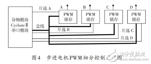
The control system adopts the bus control mode, and uses the chip select signal to sequentially control the on and off of the four PWM latches, which simplifies the hardware circuit and software design. Taking Phase A control as an example, when chip select A is high and the other chips are selected low, the A PWM latch works and the other PWM latches sleep. According to formula (8), the subdivided current distribution coefficient is calculated, which is converted into the duty ratio of the control PWM signal, and several latches are turned on at the same time, and the stepping motor is driven through the latch output.
3 Stepper motor subdivision control software design
In this design, the Quartus II software development platform and the Verilog design language are used to design the control software. In the system, linear feedback Shift Regis-ters are needed to realize the generation of random numbers in the FPGA, and the random sampling rotation of the stepping motor is controlled. The core PWM control module in this system is designed as follows:

4 system test
After the system design is completed, the entire system is tested and inspected.
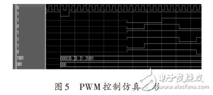
The simulation results of the PWM control system are shown in Figure 5. Observing the simulation output waveform, the control pulse output is correct. After the program is solidified into the FPGA hardware, the controlled four-phase reactive stepping motor is connected, and the FPGA is connected to the host computer through the serial port, and the output command of the upper computer controls the speed, steering, rotation angle, etc. of the stepping motor. .
5 Conclusion
This paper presents a design scheme of a stepper motor control system based on FPGA. The scheme utilizes the characteristics of fast control and high reliability of FPGA, and uses the equal step subdivision principle and PWM control technology to design a stepping motor control system with high flexibility, human-computer interaction and high resolution. The verification results show that the control system realizes 16-level subdivision of the stepping angle of stepping motor, and realizes the main technical indicators of changing the sequence of each phase through human-computer interaction, with high control precision and high reliability. This confirms the feasibility of the program.
The magnetic buzzers (Self-drive Type) offer optimal
sound and performance for all types of audible alert and identification. Our
Magnetic Buzzer solutions are offered with various mounting options. We also
provide you with a washable version for your preferred soldering method. Our magnetic buzzers, also known
as indicators, are designed with an internal drive circuit for easy application
integration. During operation, current is driven through a voice coil to
produce a magnetic field. When a voltage is applied, the coil generates a
magnetic field and then allows the diaphragm to vibrate and produce sound. This
Buzzer type has a low operating voltage ranging from 1.5 – 12V+. Our magnetic
buzzers are desirable for applications requiring a lower sound pressure level
(SPL) and frequency.
Magnetic Buzzer Self-drive Type
Passive Buzzer,Dc Magnetic Buzzer,Electro Magnetic Buzzer,Magnetic Buzzer Self Drive Type
Jiangsu Huawha Electronices Co.,Ltd , https://www.hnbuzzer.com