The power supply problem of the wireless sensor network placed in the field greatly limits the life cycle of the system. In order to extend the life cycle of the system, this paper designs a solar power supply system and introduces the power supply circuit in the wireless sensor network. The application, through the experiment to analyze the working conditions of the system, the accuracy of the measured temperature and humidity.
1 Introduction
Wireless sensor networks are a new generation of sensor networks with a wide range of applications. The nodes of the sensor network generally consist of a sensor module, a processor module, a wireless communication module, and a power module. The power module determines the life cycle of the node. Currently, a high-performance battery is generally used as the power source. However, when the battery is used up, it needs to be replaced, which increases the maintenance cost of the system. Solar power supply not only solves the power supply problem of long-term unsupervised network nodes in the field, but also has the advantages of long-lasting power supply, energy saving and environmental protection, and has a good application prospect. This paper designs an efficient solar power supply to power the wireless nodes to ensure that the system can work for a long time without replacing the battery. After the whole machine test, the power supply was successfully used in the wireless sensing system consisting of Atmega16A, nRF905 and SHT11. After testing, the system can work normally and reliably.
2. System hardware circuit design
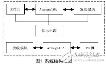
The solar-powered wireless sensing system in this paper consists of a power supply part, a sensor part, a wireless transceiver part, and a processor part. The power supply section supplies power to the entire system; the sensor section is used to measure temperature and humidity; the transceiver section is used to transmit and receive wireless data; and the processor section is used to control the sensor section, the transceiver section, and process data. The accepting part transmits the received data to the PC terminal. The structural block diagram of the system circuit is shown in Figure 1.
3. Wireless transceiver module nRF905
nRF905 is a product of Nordisk, Norway. The chip is powered by 1.9~3.6V and has a 433/868/915MHz three-band carrier frequency. It has a unique ShockBurst signal transmission mode and transmit signal carrier monitoring function, which can effectively avoid data conflicts and can be easily configured through the SPI interface. The current consumption is very low. When the transmission power is -10dBm, the emission current is 11mA, and the receiving current is 12.5mA. The advantage of nRF905 is that the circuit is simple in design, requires few peripheral devices, and can enter the sleep state when not working. The power consumption is very low.
4. Temperature and humidity sensor SHT11
The SHT11 is a single-chip fully calibrated digital relative humidity and temperature sensor with an I2C bus interface from Sensirion, Switzerland. Temperature range: -40~123°C, accuracy is 0.5°C, humidity measurement range: 0~100%RH, accuracy is 3%RH; current consumption is extremely low, 550μA when measuring, average is 28μA. After the measurement, The SHT11 automatically goes into sleep mode to save energy, making it ideal for low-power applications.
5. Power supply part design
5.1 Solar panel selection
Solar panels are mainly divided into single crystal silicon and double crystal silicon. The conversion efficiency of monocrystalline silicon solar panels is relatively high, but the processing technology is high and the price is high. The conversion efficiency of polycrystalline silicon solar cells is low and the cost is low. For cost considerations, solar panels for polysilicon are selected. Since the input power range of the selected power management chip BQ25504 is between 0~300mW and the input voltage is 0~5.5V, it can choose 300mW, the output voltage is 2V, the short circuit current is 150mA, the size is 6cm & TImes; 6cm polycrystalline silicon solar cell board.
5.2 Lithium battery selection
The choice of lithium battery depends on the total power consumption of the system and the time to continue to work. The operating current of the nRF905 is 30mA when transmitting at maximum power, and the operating current is 12.5mA when receiving. When the microcontroller Atmega16A is working at 1MHz, it works normally. The current is 1.1mA; the current consumed by SHT11 when measuring temperature and humidity: 550μA when measuring, the average is 28μA; the current consumption is about 33mA.
The lithium battery has a capacity of 2400mAh and a rated voltage of 3.7V. In the ideal case of not charging the lithium battery, the system can calculate the continuous working time: 2400mAh/33mA=72 hours, due to system software settings. It is the system that measures the temperature and humidity every hour. Assuming that the system is operated for 2 minutes, it can be calculated that the system can theoretically work continuously for about 90 days without charging the battery. The lithium battery selected in this paper is 2400mAh, 3.7V, the voltage after it is fully charged is 4.2V, and the lowest value of the discharge voltage is 2.45V, which can not overcharge and over discharge the lithium battery, otherwise it will shorten the service life of the battery, even The battery is scrapped.
5.3 Battery Management Circuit
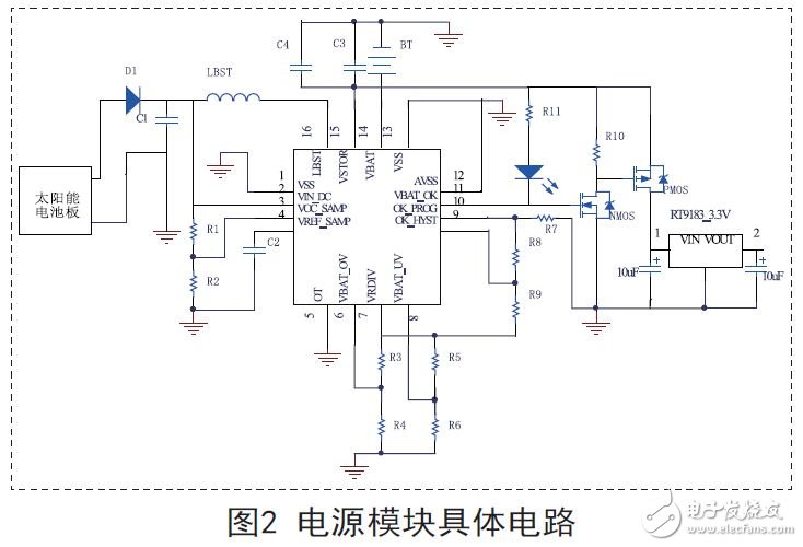
The battery management circuit is connected to the solar panel, lithium battery, and load circuit, as shown in Figure 2. Battery management circuit functions: overvoltage protection, undervoltage protection, and good battery status monitoring. This article uses the ultra-low-power boost converter BQ25504 with battery management function produced by TI Company of the United States. The chip can manage the mW generated by various energy sources, even the power supply of μW, such as solar energy, thermal energy, electromagnetic energy, mechanical vibration. Can wait. The main performance is as follows:
330nA quiescent current; over 80% high conversion efficiency; maximum power tracking technology; battery charging and discharging protection; battery status indicator. The chip is especially suitable for use in solar power systems.
Set the undervoltage threshold VBAT_UV=2.83V, overvoltage threshold VBAT_OV=4.2V, battery operating voltage range VBAT_OK_PROG=3.45V, VBAT_OK_HYST=3.96V.
According to the domain value setting formula of BQ25504, R3=5.6M, R4=4.4M, R5=5.6M, R6=4.3M, R7=3.1M, R8=5.6M, R9=1.3M when charging the battery to 4.1 V, connected to the load circuit, conduct a discharge test. After actual measurement, it is found that when the voltage of the BQ25504 pin VBAT is 3.5V and the voltage of the VSTOR pin is 0, the battery is discharged externally. Turn on the power and charge the lithium battery through BQ25504. Before charging, VBAT is 3.45V, VSTOR is 3.50V, VBATOK is 0. Actual measurement shows that when the lithium battery voltage is charged to 3.97V, the VBAT_OK output changes from 0 to 3.97V. When charging to 4.2V, the battery voltage no longer rises. During the charging process, the voltage of the VSTOR pin of the BQ25504 is slightly higher than VBAT0.05V. When VBAT_OV is reached, the two are equal; during the discharge process, the voltage of the VBAT pin of the BQ25504 is slightly higher VSTOR 0.02V.
In summary, the actual VBAT_UV=2.93V, VBAT_OV=4.2V, VBAT_OK_PROG=3.5V, VBAT_OK_HYST=3.97V, which have a deviation of about 100mV from the theoretically calculated value. The deviation between the actual value and the theoretical calculation is within 5%, which is in line with expectations. When the battery voltage VBAT is less than VBAT_OK_PROG, at this time VBAT_OK outputs a low level 0, the NMOS transistor is turned off, and the PMOS transistor is also turned off to stop supplying power to the load. When the lithium battery voltage gradually rises from VBAT_OK_PROG to 3.60V, VBAT_OK outputs a high level. At this time, the NMOS transistor is turned on, the gate of the PMOS transistor is at a low level, and the PMOS transistor is also turned on, and the load circuit can be powered until the battery voltage drops to 3.5V. In October and November 2012, the system was put out for testing. It was running for 2 months without problems. After 8 hours on a sunny day, the battery voltage could be charged from 3.5V to 4.2V.
There were more cloudy days in the past two months, but there was also sunlight in the middle. The battery voltage was 3.75V at the lowest. The system is still working normally.
6. Conclusion
The outdoor temperature and humidity values ​​measured by the system have an average temperature of 0 compared with the temperature and humidity meter. The deviation of 5 °C, the humidity has a deviation of 5% RH, the measurement accuracy has reached the general application requirements, and since the energy comes from solar energy, the system can be used for a long time. If it is used in areas with more rainy days, it can be powered by a larger capacity lithium battery or by multiple batteries.
Creative Flexible Led Display
JoyLED Creative Flexible Led Display Panels are designed specifically for delicate installations and applications, where the use of traditional LED cabinets would not be possible.
The unique Creative Flexible LED Display system features special soft but durable PCBs, which are highly flexible and allow you to create convex and concave curved displays, which can be fitted to metal frames via integral magnets in each module.
The panels are extremely lightweight and super easy to assemble with no tools required. The advanced magnetic system enables easy front accessibility and maintenance.
Get creative with our JoyLED Creative Flexible Led Display! A perfect solution for constructing seamless original LED displays with the unique ability to adapt to different structures and environments.
PRODUCT FEATURES
-
Highly flexible, ultra thin and super light
-
Designed to create convex and concave curved displays
-
Advanced magnetic connection system
-
High Brightness and Refresh rate
-
Super easy to assemble, no tools required
-
Front Maintenance

Flexible LED Display
Flexible Led Display,Flexible Led Video Wall,Programmable Led Display,Flexible Screen
Shenzhen Joy LED Display Co., Ltd. , https://www.joe-led.com