In the application of intelligent home control system, wireless communication and control have been more and more widely used. In order to achieve centralized wireless control of household electrical equipment, telephone remote control and handheld remote control can be used for remote or short-range wireless control, but the signals controlled and transmitted are all RF signals. However, some of the controlled objects are remotely controlled by infrared signals, such as TV sets and air conditioners. Since various brands of air conditioners have their own infrared coded signals, they cannot be used universally. This gives the infrared remote control in the intelligent home control system. Centralized wireless control brings great inconvenience. This article introduces the design and implementation of low-power RF / infrared controller based on MSP430.
1 Working principle
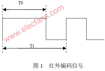
The output of most infrared remote control signals are PWM signals generated by pulse amplitude modulation of 38 ~ 40KHz square waves with encoded serial data, as shown in Figure 1. The encoded signals of infrared remote controllers of various brands are not compatible with each other [1] [2].
Measure the waveform, and store the width of the high and low levels in the Flash, regardless of how it is encoded. When the remote infrared device needs to be controlled wirelessly, the digital sequence is retrieved from the memory and restored to an infrared coded signal through the capture and comparison function module in the Msp430 microcontroller. In order to achieve wireless transmission, the signal is modulated onto 350MHz or 420MHz radio waves for transmission.
Since the frequency of the infrared coded signal is only about tens of K, and the frequency of the wireless carrier is 350MHz, the error of the above conversion is very small. The key to preventing malfunctions is the selection of the width of the pulse function. The higher the sampling frequency, the smaller the error, but the larger the memory usage. In this paper, the sampling frequency is selected to be 6 times the infrared fundamental frequency (20KHz) [6] [7].
The circuit at the receiving end first demodulates the received modulation signal to obtain an infrared waveform similar to that shown in Figure 1. This signal will drive the infrared light-emitting diode through the infrared driving circuit to obtain a remote control transmission signal to complete the required control action. As long as the demodulated signal and the actual infrared waveform have a good consistency, infrared remote control can be achieved correctly.
2 System hardware structure
The controller is divided into two parts: the main controller and the receiving node. as shown in picture 2.
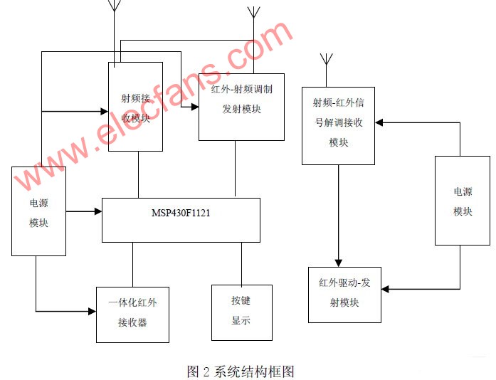
1) Power module
The main function of the power module is to achieve voltage conversion. Convert 220V alternating current into 3V and 6V direct current required for digital circuit work, of which 3V is mainly used by single chip microcomputer, 6V is used for infrared integrated receiver head and RF transmitter and receiver module. The power circuit design of this system uses a transformerless active circuit, which is mainly composed of some capacitors, resistors, diodes, voltage regulators, etc. It can achieve the indicators of small size, low power consumption, economical and practical, stable and reliable performance.
2) Controller module
The controller module uses the MSP430F1121 microcontroller as its controller. Its main function is to complete the interface with other modules, control and coordinate the work of each module. MSP430 is a 16-bit series single-chip microcomputer launched by TI, it has 4kB + 256 bytes of FLASH ROM and 256 bytes of RAM storage space. Therefore, no additional program memory is required on the entire hardware circuit. It has unique advantages in battery-powered low-power applications, its operating voltage is between 1.8-3.6V, power consumption can be controlled at about 200μA during normal operation, and low-power mode can achieve low power consumption of 2μA or even 0.1μA . When the microcontroller is in an idle state, it can be put into a sleep state to reduce power consumption. There are 6 modes to choose from: active mode (AM) and low power consumption mode (LM0, LM1, LM2, LM3, LM4), low The power consumption mode can make its minimum power consumption almost zero [3] [4].
3) Infrared self-learning module
The main function of the infrared self-learning module is to be able to learn and record infrared code waveforms in various formats. The conventional method is to store various types of infrared codes in a table, but this requires massive memory. This module is composed of the capture / comparison function module in MSP430 MCU, infrared integrated receiver head, 2 switches, one is a self-learning switch, the other is a reset switch, and LED for indication.
Figure 3 is a block diagram of the capture comparison module [5]. The capture comparison module is used to capture the time when an application event occurs, or to generate a timed interval. Using the capture function of the TImer_Ad timer, set the mode bit CAP in CCTL1, and select any transition pulse trigger mode. When the measured infrared waveform generates a rising or falling edge, the timer count value will be copied Into the capture register CCR1. The difference between the timer count values ​​recorded during two consecutive transitions is the duration of the high level or low level. Saving each time value in FLASH is to record the infrared code waveform completely. Because it is a copy of the waveform, it is possible to avoid the trouble caused by the inconsistency of the infrared coding signals sent by the infrared remote controller due to different manufacturers. Because each capture occurs, the capture / compare module register will generate an interrupt, so the program can easily determine whether the infrared waveform is over. In addition, the output unit in the capture / compare module can output a PWM waveform when it counts to CCRx and CCR0 according to the timer.

Because the MSP430 has a highly stable clock, the captured infrared code has a more accurate waveform, which can accurately reproduce the infrared code signal, and realize the self-learning and storage of the infrared code for the use of the infrared-RF modulation module.
4) Infrared-RF modulation transmitter module and RF-IR demodulation module
The module will store the time value representing the high and low level of the infrared code waveform in FLASH in advance, and put it into CCRx and CCR0 as the timer count value. When the timer counts to CCRx and CCR0, the output unit of the capture / compare module outputs PWM Waveform, through the wireless transmission module, the PWM signal is carried on a 315MHz carrier and transmitted. The wireless transmission module adopts ASK modulation, its working frequency is 315MHz, and uses the SAW resonator SAW, the frequency stability is higher.
The receiving module uses a 315MHz superheterodyne receiving module. Its advantages are stable frequency, good anti-interference ability, relatively stable performance when working with a single-chip microcomputer, and its disadvantage is relatively low sensitivity. Through this module, the received ASK signal is demodulated into a PWM signal, which is an infrared coded signal. Therefore, the infrared drive-transmission module will drive the infrared light-emitting diode to obtain the remote control transmission signal to complete the required control action.
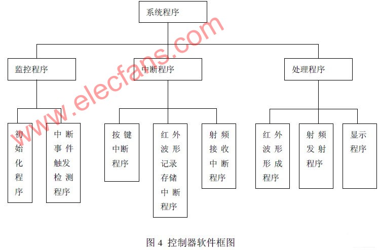
3 System software design
System software design mainly includes monitoring procedures, interrupt procedures and data processing procedures. The flow chart is shown in Figure 4. The monitoring program mainly completes the system initialization of the input and output pins of the P1 and P2 ports, interrupt settings, timer capture mode settings, etc. After the initialization procedure is completed, the MSP430F413 is set to work in the low-power mode LPM4 to put the CPU in sleep State, its energy consumption is the lowest (0.1μA). Because the P1 and P2 ports have an interrupt function, which can capture the trigger event in real time, the P2.1 and P2.2 lines are connected to the infrared learning switch, and the P2.3 is connected to the reset switch. The P1.0 and P1.1 port lines are connected to the RF receiving module, the P1.2 line receives the signal from the infrared integrated receiver, and the P1.3 port line emits infrared signals when any one of the pins receives the transition signal , An interrupt event is triggered to wake the system from sleep, which greatly saves the power consumption of the system.
The development tool selects the IAR Embebbed Workbench integrated software development system supporting TI's MSP430 series of single-chip microcomputers. It can realize online programming of the target system through the emulator, write the program to the single-chip microcomputer in real-time operation through the emulator, set breakpoints and other debugging, Through the powerful debugging window function, the operation result can be observed and analyzed.
4. Conclusion
Using the design ideas and methods of this article, the original infrared remote control device can be controlled with wireless signals. The controller has been well verified in practical applications, with high accuracy, accurate control, and strong anti-interference. Features. It provides a set of feasible solutions for the centralized wireless control of infrared remote control devices in the intelligent home control system. The author's innovation:
1 Measure the waveform of the infrared code signal, and store the width of the high and low levels in the Flash, regardless of how it is coded, it can realize the self-learning of various models of infrared remote controllers.
2 Modulate the infrared signal on the radio frequency signal, which can solve the directional shortcomings of infrared signal propagation and the problem of not being able to pass through the wall, and realize remote wireless control
3 The ultra-low power system design method provides a good solution for power-sensitive applications.
Cute Neon Lights,Color Changing Led Neon Rope Light,Led Neon Wall Lights,Flexible Neon Rope
Tes Lighting Co,.Ltd. , https://www.neonflexlight.com