introduction
Induced ventilation is to use an induced fan to eject high-speed gas to induce and drive the surrounding gas to move forward, so as to achieve the purpose of air circulation and ventilation. At present, intelligent control systems are mostly used, with complicated wiring, high cost, and inconvenient system debugging and maintenance. Power line carrier communication has the advantages of low cost and convenient debugging and maintenance, and is very suitable for inductive ventilation control systems.
1 Overall design of power line communication induced ventilation control system
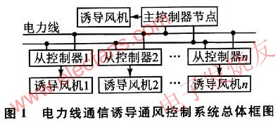
The overall block diagram of the power line communication induced ventilation control system is shown in Figure 1. The system is composed of multiple induced fan controllers. The controllers use power line communication, and each controller has the surrounding air quality status (smoke detection, CO detection). Function, and can control the operation of an induced fan according to the test results. The controller is divided into a master / slave controller. When the master controller completes the control of the induced fan, it must obtain the working status of each slave control node and control the work of the slave controller. The slave control controller controls the operation of the induced fan according to the detection result, and reports the current working status to the main controller and is controlled by the main controller. When the self control and the main controller control command conflict, the main controller control command For example, if you need to turn on the fan yourself, and the control command needs to turn off the fan, then control to turn off the fan.
2 Power line communication induction ventilation controller hardware design
2.1 Block diagram of induced ventilation controller hardware structure
The hardware structure of the power line communication induction controller is divided into smoke detection, CO detection, power line carrier communication, induction fan control, power supply unit, clock unit, storage unit, watchdog reset and keyboard display and other functional units, as shown in Figure 2. The keyboard mainly sets the system control parameters (such as CO concentration threshold, master / slave node identification, fan start / stop delay, etc.) and clock calibration. The display unit can indicate the user parameter setting process and display the current status of the system, which is convenient for the system. Installation, commissioning and maintenance. After the parameters are set, the parameters are written into the memory, and the controller starts to perform smoke detection, CO detection, induced fan control, etc. The master controller needs to periodically query the working status of each slave controller and control the slave controller to work.
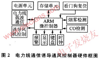
Due to insufficient oxygen supply in the working environment of the induced ventilation control system (such as a garage), if a fire is found, it will be smoldering at the beginning of the fire. If the induced fan is turned on at this time, the combustion will be an open flame. Detection of smoldering state), to avoid causing major losses caused by fan malfunctions, sound and light alarms are issued when fire danger is detected, and all fans are stopped. C0 detection is used to balance the air quality in the area. When the CO exceeds the standard, the induction fan is turned on to ensure the effect of ventilation. The controller realizes data transmission and information exchange with other controllers through the power line carrier communication unit. Due to the complicated working environment of the controller and the unattended working process, the watchdog reset unit can effectively avoid the crash and program runaway during the system working process.
2.2 Hardware circuit diagram of induced ventilation controller
Induced ventilation control processor adopts 32-bit ARM microcontroller LPC2200, which is based on ARM7TDMI-S architecture, processor clock frequency is up to 60 MHz, on-chip integrated high-speed Fl-ash memory and rich peripheral components (such as external interrupt , A / D conversion, LCD controller, etc.); the processor's own 10-bit A / D conversion can ensure the need for data collection in C0 detection and smoke detection; the processor comes with a watchdog register. Without periodic reload, an internal reset will be generated when the register overflows. The clock unit uses the clock chip SD2405AP. The chip has a built-in crystal oscillator, rechargeable battery, and has a standard I2C interface. It can be easily connected to the IPC interface of the LPC2200. Induction fan timing, delayed start / stop control, CO and smoke timing detection requirements, power line communication induction ventilation controller circuit diagram shown in Figure 3. CAT24WC02 is a serial EEPRO-M, SP708S is a microprocessor monitoring device.
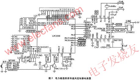
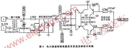
Power line carrier communication uses power line dedicated half-duplex asynchronous modem PL2102. As shown in Figure 3, the chip needs to add necessary peripheral circuits in use. The peripheral circuit mainly includes a transmission power amplifier circuit, a filter shaping circuit, a carrier coupling circuit, and a filter receiving circuit. The power amplifier circuit amplifies the carrier modulation signal output by the PL2102 and filters out noise and spurious signals in the signal. The receiving filter and power amplifier circuit are shown in Figure 4. After the output signal PSK_OUT passes through the power amplifier circuit composed of Q1, Q2, Q3, and Q4, it is added to the coupling coil through C1 and L2 filter shaping, and then sent to the power line through the coupling coil. . D1 is used for clamping in the receiving circuit to prevent excessive surge current. C2, C3 and L1 form a parallel resonance, which has the function of frequency selection for the 120 kHz signal and improves the sensitivity of the received signal.
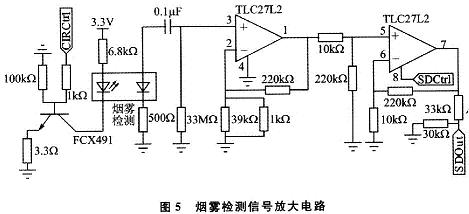
The smoke detection signal amplification circuit is shown in Figure 5. The smoke detection adopts a pair of infrared transmitting / receiving tubes, and is installed in a dark room. The two tubes are at an obtuse angle and are in a relative state. When smoke detection is required, turn on the infrared emission tube through the PO.6 port. If there is no fire hazard (no smoke), the infrared light cannot reach the infrared receiving tube; when a fire hazard (with smoke) occurs, the infrared light generates diffuse reflection and refraction on the surface of the smoke particles and enters the infrared receiving tube, the larger the smoke infrared light The stronger the diffuse reflection and refraction, the stronger the infrared light receiving tube signal. The weak signal received by the infrared receiver tube is amplified by the TLC27L2 two-stage amplification and sent to the LPC2200 for A / D conversion. The controller determines whether the fire sound and light alarm and shut down the fan operation are required by the A / D conversion value.
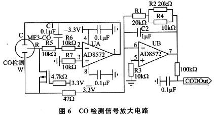
The C0 detection uses the electrochemical element ME3-CO, which obtains a weak current signal proportional to the concentration of C0 gas. This signal must be amplified before A / D conversion. The signal conditioning circuit is shown in Figure 6. The operational amplifier of the conditioning circuit adopts AD8572, in which UA, R5 ~ R7, C1 form a constant potential circuit, which keeps the potential between C and R poles and W pole constant; UB, R1 ~ R4, C2 form a signal amplification circuit for detection The current generated by the gas electrolysis in the CO sensor amplifies the weak signal of the sensor, and has a low-pass filtering function, which can filter out high-frequency interference signals in the detection signal. The amplified detection signal is input to the LPC2200 for A / D conversion, and the controller determines the air quality circulation in the current area by the size of the A / D conversion value, and controls the fan.
3 Power line communication induced ventilation controller soft
3.1 Controller induced fan control process
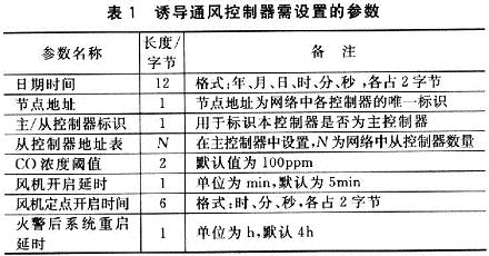
After the controller is powered on, it must first initialize the relevant software modules, including the clock chip, LCD display, A / D conversion, external interrupt, watchdog reset, etc .; after the initialization is complete, set the relevant parameters and set the parameters Write to I2C memory to save, the parameters need to be set as listed in Table 1.
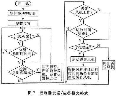
The controller detects the smoke and C0. If the smoke detection value exceeds the preset value (the smoke threshold is fixed in the program after the experimental calibration), the controller emits an audible and visual alarm, and sets the fire alarm flag, and the main controller stops all For the fan, the length of time to recover from the "fire alarm state" is determined by the parameter "System restart delay after fire alarm". The master controller queries the working status of each slave controller at intervals of 5s. When a fire is detected in a certain area, the control stops all fans, and the slave controller modifies the current working state. The program control flow of the controller to the induced fan is shown in Figure 7. The controller displays the current status of the fan, smoke and CO detection values, whether there is a fire, whether the CO exceeds the standard, and the working status of the system (working status of each main component, such as clock chip operation, A / D conversion, communication) during operation.
3.2 Power line carrier communication program flow
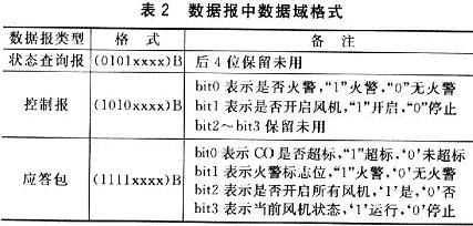
The master / slave communication is adopted between the master controller and the slave controller in the system. The communication process is initiated by the master controller. The master controller sends the report into "status inquiry report" and "control report". The slave controller receives the master control After the device data report, it needs to be returned to answer the report. Considering the convenience of software design, the sending message and the reply message use the same message format. The message format is as follows:
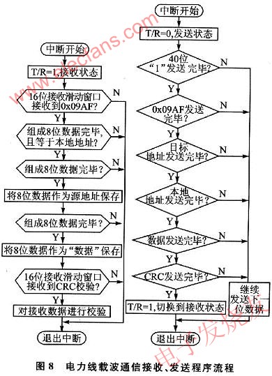
In the message format, 40 “1†s are used to synchronize the pseudo-random code of the receiving end and the sending end, the frame header sequence is fixed at 0x09AF; the source address is the node address of the sending datagram, and the target address is the datagram needs to be delivered The node address of the data; the data is the information to be transmitted by the data report, accounting for 1 byte, the high 4 bits are the report type, the low 4 bits are the data information, and the data field format is as listed in Table 2; CRC16 is the source address, target address, The CRC check value of the data.
The carrier communication program uses an interrupt mode, which is divided into two parts: sending and receiving. The interrupt signal is generated by the PL2102 synchronous pulse output pin (HEAD). The carrier communication receiving and sending program is shown in Figure 8.
Conclusion
Induced ventilation control system based on power line communication, dedicated power line carrier communication chip is used in hardware design, power amplification and receiving filter circuits are applied in signal transmission and reception, and data check CRC16 is used in software to ensure the reliability of communication. The design scheme has the advantages of simple system construction, low cost, and convenient debugging and maintenance.
Ncm Battery,Lithium-Ion Battery With Ncm Material,18650-2800Mah Battery,Nicomn Lithium Battery
Henan Xintaihang Power Source Co.,Ltd , https://www.taihangbattery.com