Abstract: This application note details how to use the MAX6958 and MAX6959 LED display drivers to achieve pixel-level (single LED) brightness control. This technology enhances the 64-level overall (adjust all LEDs at once) brightness control functions built into these drivers.
Introduction The MAX6958 and MAX6959 LED display drivers use 6-bit PWM (64-level) brightness control technology while adjusting the average current of all lit LEDs. This application note discusses how to extend the functions of the MAX6958 and MAX6959 to achieve individual pixel-level (LED) control. The connection method of the multiplexed LED driver in the average LED current mode MAX6958 and MAX6959 are 4-bit, 9-segment LED drivers, using a multiplexing technology with a smaller number of pins (Charlieplexing-please refer to Charlieplexing for technical details- Reduced Pin-Count LED Display MulTIplexing), driving 36 segments using only 10 driving pins (Table 1). As shown in Table 1, the connection method of the MAX6958 / MAX6959 pins and LED bits is different from the standard connection method. Depending on the time slot of the multiplexing cycle, pins 4 to 7 act as common cathode drivers or anode drivers.
Table 1. MAX6958 / MAX6959 standard driver connection method
The MAX6958 / MAX6959 use a four-way multiplexing drive scheme, which alternately drives the cathodes of four groups of LEDs, and each group includes nine LEDs. The four groups of LEDs are called bit 0, bit 1, bit 2, and bit 3, respectively. The four cathode connection points from the 0th to the 3rd position of the LED correspond to CC0 to CC3 in Table 1, and the anode connection point of the LED is prefixed with SEG. In the normal multiplexing mode of operation, the CC0 to CC3 cathode outputs turn lower in turn, and each bit sequentially enables a quarter cycle.
The 6-bit (64-level) PWM overall brightness control function adjusts the average current of the LED (thus adjusting the brightness). This is achieved by adjusting the actual time that the cathode outputs CC0 to CC3 are turned on in their multiplexed time slots. The PWM values ​​loaded to the cathode outputs of CC0 to CC3 are the same, and the constant current source of each anode driver is not separately adjusted. Therefore, the brightness of all LEDs are adjusted uniformly. Implementing individual LED brightness control In many applications, highlighting specific LEDs is very useful. Blinking is a method of highlighting, and cursors often use blinking methods to highlight their positions. Another good way to highlight is to make these LED segments brighter than other LEDs. If the above-mentioned MAX6958 / MAX6959 standard multiplexing structure is used, the latter method will not work.
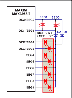
A simple method to achieve individual brightness control of the LED segment is to allow the LED driving time to exceed one multiplexing cycle, that is, dual driving. Figure 1 illustrates this point, that is, a single, 7-segment plus decimal point digital tube position is driven by the usual two bit control signals of the 0th and 1st bits of the LED. Note that Figure 1 is incomplete. The second and third LED bits are not drawn; they can be another single bit or two bits in the standard way.

Figure 1. The MAX6958 / MAX6959 connection method that drives a digital tube and has 2-level independent brightness control
The driving time of the dual-drive bit shown in Figure 1 is two multiplexing cycles, rather than the usual one cycle. At this time, diodes D1 and D2 control the two cathode drivers. Whether CC0 or CC1 goes low as the cathode driver, they operate the same LED. Because a single dual driver bit replaces two standard driver bits, it is controlled by two bit registers (bit 0 and bit 1, corresponding to 0x20 and 0x21, respectively), rather than being controlled by only one bit register. Each LED is represented by two bits (one bit per bit register) instead of one bit. If both bits are cleared, the LED turns off. If only one bit is set and the other bit is cleared, the LED turns on at standard brightness. If both bits are set, the LED turns on at twice the standard brightness. Therefore, each LED has two brightness settings instead of one. LEDs connected in a standard way, such as SEG0 and SEG1, can only be set to standard brightness. Since diodes D1 and D2 flow 20mA for each of the 8 LEDs in a quarter of the time, the rated peak current of the diode must reach 160mA and the average current reaches 40mA.
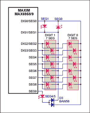
The connection in Figure 1 has its tradeoffs. The number of digits driven by the MAX6958 / MAX6959 is reduced here, because each LED with two brightness settings requires the drive capability of two "standard" LEDs. To make each pixel have two brightness settings, the MAX6958 / MAX6959 can only drive two 7-segment digital tube positions instead of only four bits with standard on / off control functions. But for occasions where only a few LEDs require brightness control, the technology is still very effective and economical. Figure 2 shows that a single LED adopts a dual driving scheme, and only needs to sacrifice the driving ability of one LED. The diode pair D3 only needs to flow 20mA current for one LED, and the peak value is 20mA. Therefore, low-cost signal diode pairs can be used.

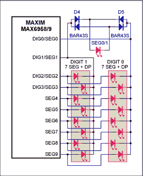
Figure 2. The MAX6958 / MAX6959 connection with only one LED with 2-level independent brightness control. Another way to achieve independent LED brightness control is to replace the back-to-back LEDs SEG0 and SEG1 with a diode to achieve 2-level brightness control. As shown in Figure 3, the diode bridge rectifies the back-to-back drive current. Since two diodes are connected in series in the LED current path at this time, a small-signal Schottky diode needs to be selected to reduce the voltage drop.

Figure 3. Another MAX6958 / MAX6959 connection with only one LED with 2-level independent brightness control
Introduction The MAX6958 and MAX6959 LED display drivers use 6-bit PWM (64-level) brightness control technology while adjusting the average current of all lit LEDs. This application note discusses how to extend the functions of the MAX6958 and MAX6959 to achieve individual pixel-level (LED) control. The connection method of the multiplexed LED driver in the average LED current mode MAX6958 and MAX6959 are 4-bit, 9-segment LED drivers, using a multiplexing technology with a smaller number of pins (Charlieplexing-please refer to Charlieplexing for technical details- Reduced Pin-Count LED Display MulTIplexing), driving 36 segments using only 10 driving pins (Table 1). As shown in Table 1, the connection method of the MAX6958 / MAX6959 pins and LED bits is different from the standard connection method. Depending on the time slot of the multiplexing cycle, pins 4 to 7 act as common cathode drivers or anode drivers.
Table 1. MAX6958 / MAX6959 standard driver connection method
| DIG0 / SEG0 | DIG1 / SEG1 | DIG2 / SEG2 | DIG3 / SEG3 | SEG 4 | SEG 5 | SEG 6 | SEG 7 | SEG 8 | SEG 9 / IRQ | |
| LED Digit 0 | CC0 | SEG 0 | SEG g | SEG f | SEG e | SEG d | SEG c | SEG b | SEG a | SEG 4 |
| LED Digit 1 | SEG 1 | CC1 | SEG g | SEG f | SEG e | SEG d | SEG c | SEG b | SEG a | SEG 5 |
| LED Digit 2 | SEG g | SEG f | CC2 | SEG 2 | SEG e | SEG d | SEG c | SEG b | SEG a | SEG 6 |
| LED Digit 3 | SEG g | SEG f | SEG 3 | CC3 | SEG e | SEG d | SEG c | SEG b | SEG a | SEG 7 |
The MAX6958 / MAX6959 use a four-way multiplexing drive scheme, which alternately drives the cathodes of four groups of LEDs, and each group includes nine LEDs. The four groups of LEDs are called bit 0, bit 1, bit 2, and bit 3, respectively. The four cathode connection points from the 0th to the 3rd position of the LED correspond to CC0 to CC3 in Table 1, and the anode connection point of the LED is prefixed with SEG. In the normal multiplexing mode of operation, the CC0 to CC3 cathode outputs turn lower in turn, and each bit sequentially enables a quarter cycle.
The 6-bit (64-level) PWM overall brightness control function adjusts the average current of the LED (thus adjusting the brightness). This is achieved by adjusting the actual time that the cathode outputs CC0 to CC3 are turned on in their multiplexed time slots. The PWM values ​​loaded to the cathode outputs of CC0 to CC3 are the same, and the constant current source of each anode driver is not separately adjusted. Therefore, the brightness of all LEDs are adjusted uniformly. Implementing individual LED brightness control In many applications, highlighting specific LEDs is very useful. Blinking is a method of highlighting, and cursors often use blinking methods to highlight their positions. Another good way to highlight is to make these LED segments brighter than other LEDs. If the above-mentioned MAX6958 / MAX6959 standard multiplexing structure is used, the latter method will not work.
A simple method to achieve individual brightness control of the LED segment is to allow the LED driving time to exceed one multiplexing cycle, that is, dual driving. Figure 1 illustrates this point, that is, a single, 7-segment plus decimal point digital tube position is driven by the usual two bit control signals of the 0th and 1st bits of the LED. Note that Figure 1 is incomplete. The second and third LED bits are not drawn; they can be another single bit or two bits in the standard way.

Figure 1. The MAX6958 / MAX6959 connection method that drives a digital tube and has 2-level independent brightness control
The driving time of the dual-drive bit shown in Figure 1 is two multiplexing cycles, rather than the usual one cycle. At this time, diodes D1 and D2 control the two cathode drivers. Whether CC0 or CC1 goes low as the cathode driver, they operate the same LED. Because a single dual driver bit replaces two standard driver bits, it is controlled by two bit registers (bit 0 and bit 1, corresponding to 0x20 and 0x21, respectively), rather than being controlled by only one bit register. Each LED is represented by two bits (one bit per bit register) instead of one bit. If both bits are cleared, the LED turns off. If only one bit is set and the other bit is cleared, the LED turns on at standard brightness. If both bits are set, the LED turns on at twice the standard brightness. Therefore, each LED has two brightness settings instead of one. LEDs connected in a standard way, such as SEG0 and SEG1, can only be set to standard brightness. Since diodes D1 and D2 flow 20mA for each of the 8 LEDs in a quarter of the time, the rated peak current of the diode must reach 160mA and the average current reaches 40mA.
The connection in Figure 1 has its tradeoffs. The number of digits driven by the MAX6958 / MAX6959 is reduced here, because each LED with two brightness settings requires the drive capability of two "standard" LEDs. To make each pixel have two brightness settings, the MAX6958 / MAX6959 can only drive two 7-segment digital tube positions instead of only four bits with standard on / off control functions. But for occasions where only a few LEDs require brightness control, the technology is still very effective and economical. Figure 2 shows that a single LED adopts a dual driving scheme, and only needs to sacrifice the driving ability of one LED. The diode pair D3 only needs to flow 20mA current for one LED, and the peak value is 20mA. Therefore, low-cost signal diode pairs can be used.

Figure 2. The MAX6958 / MAX6959 connection with only one LED with 2-level independent brightness control. Another way to achieve independent LED brightness control is to replace the back-to-back LEDs SEG0 and SEG1 with a diode to achieve 2-level brightness control. As shown in Figure 3, the diode bridge rectifies the back-to-back drive current. Since two diodes are connected in series in the LED current path at this time, a small-signal Schottky diode needs to be selected to reduce the voltage drop.

Figure 3. Another MAX6958 / MAX6959 connection with only one LED with 2-level independent brightness control
Silicon Transistor are solid-state semiconductor devices with functions such as detection, rectification, amplification, switching, voltage regulation, and signal modulation. The transistor acts as a variable current switch and can control the output current based on the input voltage. Unlike ordinary mechanical switches (such as Relay and switch), transistors use electrical signals to control their opening and closing, and the switching speed can be very fast. The switching speed in the lab can reach more than 100GHz.
Silicon Transistor
Silicon Transistor, Power Transistor, IGBT Transistor, N-Channel Transistor, PNP Transistor
YANGZHOU POSITIONING TECH CO., LTD. , https://www.yzpst.com