1 Introduction
UPS, uninterruptible power supply, means that the power supply can provide a reliable and stable power supply form under normal or faulty mains conditions. It is often used to provide the most power failure protection for loads in some critical loads such as computer rooms and hospitals. However, traditional online UPS has multiple power sections and analog controllers, which is a very complicated and expensive system. Therefore, the research on high-quality, high-reliability all-digital UPS (uninterruptible power supply) suitable for the development of modern technology has become a topic of great concern. Digital control has become a hot spot in the field of power supply research because of its simple and flexible control, more stable output performance, and the ability to achieve functions that are difficult to achieve with analog control. With the development of microelectronics technology, more and more solutions have been provided for power electronics, and the introduction of all-digital systems and various advanced control strategies for UPS power supplies has gradually become a reality.
This paper mainly discusses one of the key technologies in the UPS based on the TMS320LF2407 digital control platform - phase-locked control technology.
2. Locked meaning
There are two switches during the operation of the uninterruptible power supply:
First, the power supply is bypassed to the load when the power is started, the inverter runs at no load, and the phase lock function is started at the same time. The inverter output is adjusted to track the grid frequency and phase. When the inverter output tracks the grid frequency, the inverter is switched to the load. Power supply; second, when the inverter circuit fails, or when the load is impactful (such as when starting the load) or overload, the control system will block the PWM output to stop the inverter from supplying power to the load, and at the same time turn on the bypass switch. The grid supplies power directly to the load.
In order to effectively ensure that the inverter bypass switching process does not have an excessive impact on the load, the UPS inverter output voltage must be consistent with the frequency and phase of the grid voltage. Therefore, the UPS system introduces phase-locked control technology, and software phase-locking technology is one of the important links of digital UPS. The fast and reliable software phase-locked tracking technology can accurately provide the standard voltage reference sine wave with the same frequency as the grid voltage for the digital control of the inverter.
3. Basic principle of phase-locked loop
The phase-locked loop is a closed-loop phase control system that automatically tracks the frequency and phase of the input signal. It consists of a phase comparator, a low-pass filter, and a voltage-controlled oscillator. The control block diagram is shown in Figure 1.
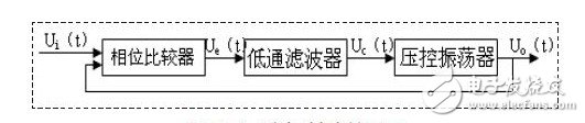
Figure 1: Phase-locked control block diagram
The working principle is as follows: the output signal uo(t) of the voltage controlled oscillator and the sampling signal ui(t) of the power grid are sent to the phase comparator, and the amplitude of the generated error signal ue(t) is generated. It is proportional to the phase difference between the uo(t) and ui(t) signals. After ue(t) is processed by the low-pass filter, a control voltage signal uc(t) corresponding to the average value of the ue(t) signal is sent out, and the voltage-controlled oscillator is adjusted under the control of the signal uc(t). The frequency and phase of the voltage signal uo(t) are output, so that the frequency and phase difference of the two signals uo(t) and ui(t) are gradually reduced.
4. In-line UPS phase-locked control technology
According to the difference of the SPWM wave mode generated by the control circuit of the single-phase UPS inverter, the method of implementing the phase lock control of the UPS is very different, which are discussed separately below.
4.1 Analog Phase Locking Control Technology for Online UPS
The traditional online UPS power supply, its phase lock control principle block diagram shown in Figure 2. When the power supply is normal, the grid voltage detection circuit outputs a high level, and the 50 Hz grid voltage is converted into a unipolar "inverted full-wave rectification" signal with a period of 20 ms via a waveform conversion circuit, and then sent to the input end of the analog switch 1, after simulation. After the switch 2, a series of grid voltage synchronization tracking signals are generated. Since the output signal of the inverter is a synchronous capture signal with a period of 20ms, the grid synchronous tracking signal applied to the control end of the multivibrator can adjust the phase of the high frequency output pulse of the high frequency oscillator to ensure sine wave generation. The device outputs a 50 Hz reference sine wave. After the phase-locked synchronization circuit, that is, the "phase-locked loop", the sine wave is always in the same tracking state as the grid voltage in the same frequency. When the power supply is abnormal, the multi-vibrator generates a signal with a local oscillation frequency of 20 kHz, outputs a 500 Hz pulse sequence through the frequency divider, and then generates a frequency-stabilized 50 Hz standard sine wave through the sine wave generator.
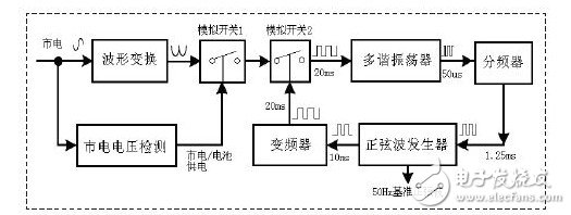
Figure 2: Schematic diagram of online UPS power phase lock control with output transformer
The traditional sine wave signal generator uses a feedback oscillating circuit to output a sine wave by self-oscillation and frequency selection of the circuit, but the low frequency analog oscillator has a disadvantage:
Due to the influence of voltage and temperature, the frequency and amplitude stability of the output signal are poor, it is difficult to meet the requirements as an AC reference; and the control circuit structure is quite complicated by the use of the analog device, which is inconvenient to produce and difficult to debug.
4.2 Digital Phase Locking Control Technology for Online UPS
In the digital phase-locked control technology of online UPS, the microprocessor is used as the core control chip, and the method of phase latching is implemented by software. The circuit generally consists of the following parts: AC voltage transformer, precision rectifier circuit, zero-crossing comparison , low pass filter, inverter, analog switch and microprocessor. Its circuit block diagram is shown in Figure 3.
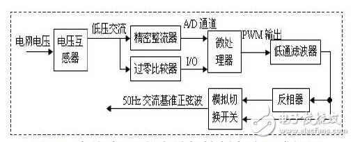
Figure 3: Block diagram of the online UPS digital phase lock control circuit
The working principle of the circuit is: the AC voltage of the power grid is isolated and stepped down by the voltage transformer to become a low-voltage AC signal with the same frequency and the same frequency as the grid voltage, and the first phase passes through the precision rectifier circuit to become a positive half-wave DC voltage signal, which passes through the internal A of the microprocessor. /D converter, measuring the amplitude of the voltage; the other way through the voltage zero-crossing comparator output positive and negative polarity of the AC signal, enter the MCU through the I / O port, so that the real-time waveform data of the external AC voltage can be measured, A sine wave can be output by D/A conversion of the acquired waveform digital sequence. Since the grid voltage contains a large amount of harmonic components, the AC voltage signal collected by the voltage transformer is not a pure sine wave, so the waveform generated by the direct output method is not a stable and pure sine wave.
Therefore, a digital low-pass filter is added after the PWM output to filter out high-frequency harmonic components, thereby ensuring the stability and purity of the output voltage.
The specific implementation process is as follows: First, the PWM pulse width modulation circuit inside the single chip is modulated by a digital sequence, so that the pulse square wave width generated is proportional to the signal amplitude. If the microprocessor uses a 20 MHz crystal oscillator and the PWM output is 8-bit resolution. The maximum frequency of the output square wave is 78KHz, so an RC low-pass filter with a small integral constant is added to the PWM output to obtain a smooth half-wave output waveform, and the phase delay caused by the low-pass filter is negligible. The signal is sent directly to the analog switch, and the other circuit is sent to the inverter circuit to become a negative half-wave voltage signal, and then sent to the analog switch. The positive and negative two-way voltage signals are switched by the analog switch controlled by the single-chip microcomputer, and the output is output. A sine wave signal with phase synchronization of the external grid. When the grid fails, the microprocessor reads a standard 50 Hz sine wave sequence stored in its memory to control the inverter output.
4.3 Software Phase Lock Control Technology for Online UPS
With the development of microelectronics technology, many cost-effective dedicated microprocessors for motor control have emerged. The PWM integrated circuit is integrated inside the microprocessor, and the PWM wave output frequency can be changed by software programming. Software phase-lock control in UPS is based on such a microprocessor, implemented in program calculation. There are two ways to implement the software. One is that the two signals of the mains voltage and the inverter output voltage need to be filtered and shaped, converted into a square wave signal of the same frequency, and the jump of the rising edge of the square wave is captured by the capture pin of the microprocessor, and the captured value is captured. To calculate the frequency and phase difference, to adjust the frequency of the output SPWM wave, so that the frequency and phase of the two signals are consistent, and the block diagram of the phase-locked synchronous control is shown in Figure 4. Another method only needs to perform square wave conversion on the mains voltage. In the capture interruption of the mains conversion square wave, by changing the phase of the SPWM output wave relative to the lead phase of the mains phase, the SPWM timer period is changed. The value is used to adjust the output frequency of the SPWM wave period to achieve frequency tracking.
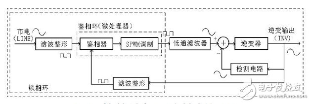
Figure 4: Software Phase Lock Synchronization Control
The commonality of the two methods is: the grid voltage frequency is set to 50Hz in advance, and each voltage period is divided into N equal parts according to the SPWM carrier frequency (when the carrier frequency is 78KHz, N=150), which will correspond to the time. The sinusoidal value is formed in the memory of the microprocessor, and the number of output sequences per SPWM period is kept constant. The carrier frequency is adjusted to adjust the output voltage frequency; their implementation depends on two interrupts, one is The SPWM carrier cycle timer interrupt, one is the capture interrupt (the capture interrupt can be set to cause the capture interrupt to occur at the zero phase of the sine wave period).
Since both methods are used to adjust the SPWM frequency to achieve the phase-locked output to the mains voltage, the tracking accuracy is higher in steady state, but the dynamic performance is not good, and the tracking adjustment speed is slower when the phase-locked loop is started. The synchronous response speed needs to be improved, and the anti-interference and fault tolerance of the synchronization needs to be further enhanced.
5 Conclusion
The software phase-locking technology of UPS based on TMS320LF2407 digital control platform studied in this paper has high phase-locking precision and is easy to implement, which can well meet the phase-locking technical requirements of uninterruptible power supply.
Shenzhen Jiesai Electric Co.,Ltd , https://www.gootuenergy.com