Introduction Asymmetric digital subscriber line (ADSL) systems are the most popular form of consumer DSL systems currently deployed. It can support data rates up to 12 Mbps in shorter loops. When the loop lengthens to 5.5Km or longer, by adjusting its rate and spectrum, a meaningful data rate can still be achieved. However, many interferences reduce the coverage of ADSL, which creates loopholes in the network and cannot achieve acceptable service rates.
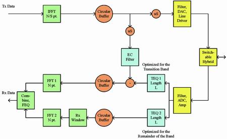
Figure 1 Example of a modem architecture optimized for longer loops
This article will introduce some ADSL modem design techniques to compensate for the above-mentioned interference, including inter-symbol interference (ISI), bridge taps and radio frequency interference (RFI), etc., as well as improved transmission spectrum based on the realization of longer coverage, minimize crosstalk and solve Some new standards for hybrid central office (CO) and remote terminal (RT) deployment issues. The continuous development of new standards, coupled with the introduction of a flexible modem architecture, the combination of the two allows operators to expand the field of DSL services provided at a certain target rate.
ADSL basics
ADSL uses discrete multi-tone (DMT) modulation to convert a single broadband communication channel into multiple narrowband subchannels.
If the channel memory does not exceed the length of the cyclic prefix, the cyclic prefix (the signal after the IFFT is connected to the block to be transmitted) can achieve simplified equalization of the receiver. In this case, equalization is just a complex multiplication on a sub-channel by sub-channel basis, thereby eliminating channel effects.
For the case where the channel memory is larger than the cyclic prefix, a channel shortening filter (called a time domain equalizer or TEQ) is usually used in the designed receiver, so that most of the power of the TEQ in series with the channel is limited to the cyclic prefix length +1 . This is in contrast to the single-channel case, where the linear equalizer usually designs the minimum mean square error as a flip channel.
A typical ADSL deployment is frequency division duplex (FDD). A single channel (twisted pair) is used to carry two signals and is connected to the transmitter and receiver of each modem through a hybrid circuit. Broadly speaking, hybrid circuits use isolation transformers for four-to-two line conversion. More specifically, the hybrid circuit performs analog echo cancellation to reduce transmission signal (or echo) reflection in the receiver. Hybrid echo suppression depends on the impedance of the reflected line (via the transformer), and it varies according to different loop topologies.
Interference compensation
The ADSL channel is affected by various interferences, and sometimes the data rate may even be so low that ADSL cannot be used from a commercial point of view (for example, it is difficult for us to market the 32 kbps rate as broadband). This section will study ISI, bridge taps, and RFI, and analyze how to use appropriate modem design to limit the impact of interference on the ADSL system.
ISI
The ISI in the ADSL channel is the result of the combination of twisted pair media and FDD filters. TEQ, which works well when the ISI is strong near the transition zone, may have grooves in frequency. As noise propagates from the FFT, the notch causes loss of SNR, which reduces the data rate.
One solution to the above problem is to use multiple receive paths with independent channel shortening equalizers, each of which optimizes different parts of the channel. For example, one TEQ can be designed for the transition band with strong ISI, while the other TEQ can be designed for the rest of the frequency band, where the ISI will be weaker, which is conducive to obtaining a smoother frequency response. After the FFT, the outputs of the two channels are combined to form a single output of the subchannel (this is as simple as making a choice between the two channels).
Bridge taps Bridge taps refer to multiple distribution cables connected to a single feeder cable. Only one distribution cable is connected, the others remain open. Although this architecture allows operators to flexibly distribute lines, the bridge taps will cause impedance matching problems and reflection problems in the channel. Depending on the architecture, wiring in the home will have a similar effect.
The reflection of the transmitted signal caused by the bridge tap causes the echo component in the received signal to increase. Even if the ADSL system works in FDD configuration, the enhanced echo (if not compensated) will cause the data rate to decrease. This is because in the case of a long loop, the echo power will be greater than the received signal power, which actually limits the gain setting of the receiver, which increases the effective noise level of the modem. Furthermore, the diffusion from the FFT allows one frequency band to spread to other frequency bands, which seems to have an additional source of noise. Although the use of a sensitive band separation filter can help reduce the amount of diffused echoes, its disadvantage is that it will cause equalization problems for other receivers. In addition, it cannot solve the problem of modem noise level. Therefore, when dealing with additional echoes caused by bridge taps, a more reasonable approach is to take two steps.
First, in order to optimize the receiver dynamic range, the hybrid circuit must be adjusted to accommodate the different reflected line impedances caused by the changing loop topology. In the simplest implementation, multiple hybrid circuits can be used for different loop topologies to achieve this.
For the hybrid circuit matching echo components that have not been removed, an echo canceller (EC) can be used to remove the remaining echo signals. The ADSL system can be designed to use traditional EC in the time domain, or to perform echo cancellation in the frequency domain (using some form of cyclic echo synthesis).
RFI
RFI is caused by radio frequency signal coupling in the ADSL frequency band (0 ~ 1104 or 2208KHz). If the AM radio is coupled into the signal due to the fact that the twisted pair and modem front-end cannot be fully balanced, the spread of the sinusoidal interference signal of the FFT may cause the data rate to drop in many sub-channels. Therefore, it is necessary to develop some algorithms for processing RFI.
The main standard of TEQ design is to shorten the channel, and the TEQ design based on MMSE is to handle zero at the position of the stronger RFI source. Although zero-setting will reduce the rate a bit, generally speaking, noise diffusion will be greatly reduced, and the cost of the rate reduction is also reasonable. In this way, if there is an RFI source when calibrating TEQ, TEQ can be used to compensate the RFI.
Opening the receiver window is the second method available for RFI compensation. The receiver opens a window using the information in the cyclic prefix to form a window. It will affect the noise. As long as the channel memory is shortened to the cyclic prefix minus the length of the window, it will not affect the signal. In this way, we get a window with side lobes, which decay much faster than a rectangular window. Therefore, even if the RFI appears after the modem is calibrated, the modem still shows high immunity to the harmful effects of RFI. The price it pays is the additional restrictions (lower degrees of freedom) caused by the shortening of the channel.
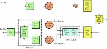
Figure 2 modem architecture optimized for short loop (ADSL2 +). Please note that the combination of the two paths of the modem optimized for long loops constitutes TEQ and FFT operations
Performance improvement based on transmission spectrum Since ADSL is based on DMT modulation, it has great flexibility in forming transmission bands. We can use this flexibility to improve the coverage of ADSL systems, to handle hybrid CO and RT deployments, and to minimize crosstalk.
Broader spectrum shaping
The common shape of the DSL channel makes the attenuation of high frequencies greater than low frequencies. In addition, the channel attenuation increases as the loop length increases. Since FDD ADSL systems allocate higher frequencies to the downstream to improve the performance of ADSL over longer loops, it is usually necessary to increase the downstream data rate.
ADSL2 is the second generation of ADSL, which solves the above problems with specific accessories (range extension ADSL2), that is, spectrum shaping is used to place the power in a better place in the channel or overlap the upstream and downstream. Implementation, and the latter requires an EC. In addition, the uplink power can reduce the frequency to avoid crosstalk and reduce the incoming downlink echo.
ADSL2 + handles CO and RT
Mixed deployment scenarios Local loop unbundling makes it possible for one operator to provide services in a certain area from CO and another operator to provide services in the same area from RT. Because RT may be much closer to the end user than CO, the crosstalk caused by RT will seriously affect the performance of the ADSL system running on CO. Depending on the distance between CO, RT and the end user, as well as the coupling between different lines, the performance impact will vary.
ADSL2 + is a high-speed version of the new ADSL standard, and its downstream bandwidth doubles in width, providing a possible solution for the mixed deployment of CO and RT. The basic idea is to make the formation of ADSL2 + spectrum (may only need to close the sub-channel) to minimize crosstalk caused by lower frequencies. Due to the short loop, the ADSL2 + system deployed by RT can achieve a more reasonable rate even with only a higher sub-channel. Corresponding to this, if the ADSL system deployed by CO is limited to lower subchannels by the ring attenuation on the long loop, then the system will have less crosstalk from the ADSL2 + system deployed by RT, so it can still achieve a more reasonable s speed.
Minimize crosstalk
ADSL2 follows the principle of being a good neighbor in the existing system (co-RT deployment is an example), and provides more ways to minimize crosstalk. This includes the use of a power reduction mechanism based on the upper limit to remove power while still maintaining the same data rate; it also includes the L2 mode that reduces the transmission power when there is less data, and can be repeated through bit loading changes that fully control the playback time Iterative water filling to minimize crosstalk.
Flexible architecture For the compensation of various interferences in long loops, two paths can be used based on the ISI observed on different parts of the channel. EC can be used for a path specifically designed for the transition zone (this is where the echo is the most), and the receiver window or TEQ design that reduces RFI can be used for another path because the above interference will appear outside the transition zone (see Figure 1) .
For shorter loops that cause less interference, the two paths can be combined to double the number of sub-channels that the system can handle. Assuming that the number of doublings per cycle that TEQ can provide is constant, each of the two lengths L TEQ works at the R sampling rate per second, and the combination of the two adds the smallest logic, you can get a single work at 2R rate Length L TEQ (split the filtering operation into two parts and use delay). In addition, the parity samples of the TEQ output can be routed to an independent FFT of N size, and the two FFT outputs can be combined together, plus an additional butterfly stage to generate an FFT of size 2N (basically following the time FFT derivative Extraction). In this way, you get a modem that can achieve short-loop high-efficiency, high-speed operation, and can handle a large number of long-loop interference (see Figure 2).
Conclusion Expanding the coverage of ADSL modems by combining flexible modem design with the new ADSL standard. This article summarizes some methods of compensating for general interference, plus the flexibility in the ADSL transmission spectrum, which can greatly increase the data rate for all loop lengths.
2 In 1 Laptop
Do you know the difference of Yoga Laptop and 2 in 1 laptop? No. 1 is yoga notebook with 360 flip rotating absolutely; No.2 is laptop yoga slim is just like normal Education Laptop-connecting screen with keyboard, but 2 in 1 laptop tablet with pen is separately, you can use the monitor part as a window tablet. In one word, every intel yoga laptop have all the features and function of tablet 2 in 1 laptop except separated screen and keyboard. From the cost, windows yoga laptop is much higher than 2 in 1 type., cause usually former with more complicated craft and quality.
What other products you mainly produce? It`s education laptop, Gaming Laptop, engineering laptop, Android Tablet, Mini PC and All In One PC. You can see more than 5 different designs on each series, believe always have right one meet your special application or your clients demands. Therefore, what you need to do is just to get all the requirement details from your clients, then share the complete information with us, then we can provide the most suitable situation.
Of course, you can also call or email or send inquiry of what you need, thus can get value information much quickly.
2 In 1 Laptop,2 In 1 Laptop Sale,2 In 1 Laptop Tablet With Pen,Tablet 2 In 1 Laptop,2 In 1 Laptop Deals
Henan Shuyi Electronics Co., Ltd. , https://www.shuyioemelectronics.com